Thx for all the help and tips so far. You guys are a great bunch.
Structo, I do have a solder sucker. Mine is the smaller one, but it's metal and it's pretty nice. I used to have a plastic one that sucked. (No pun intended)
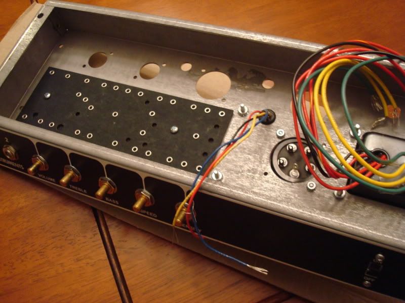
I got the holes done and it was no big deal as I thought. Drilling the chassis was quite easy after I center punched the hole.
I also drilled through the tagboards the holes I needed so Im back on track.
There was nothing the drilling the chassis. The center punch and the drill bit worked fine. I was fuzzing over nothing...
The tagboard was really easy to drill as well. I drilled 3 holes in it. It was missing one for the leads and the two mounting holes.
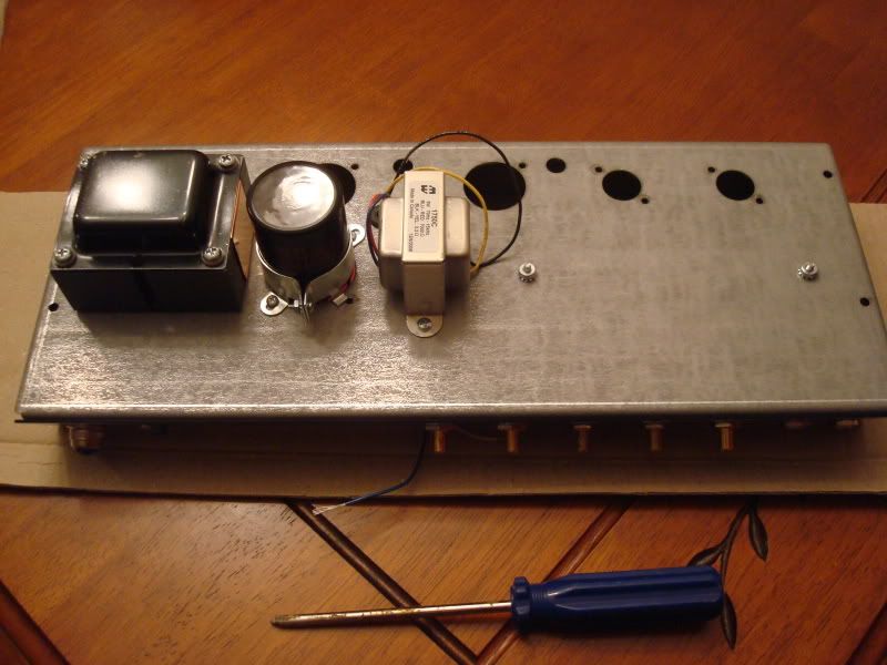
I also had to enlarge the holes both in the chassis and the clamp for the cap can to get it to fit properly. The holes wouldn't line up. So I just made them longer on the clamp and slightly bigger on the chassis.
Now I need to make me a chassis holder to make things easier..
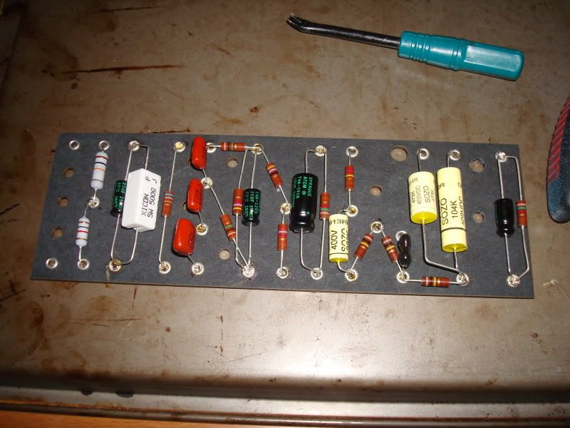
Board completely populated. I tried to be as neat as possible but I kinda messed up at a few spots due to my lack of experience. I cut the leads a bit too short on one of the spragues caps but managed to get it to work. I should have soldered the leads as well, but I didn't cuz that required too much concentration, so I'll solder them later.
I know you haven't soldered it yet, but it looks like the big power resistor is touching the cap. Those things get hot. So it's usually good to raise them and have some space between the resistor and the cap.
FunkyE9th wrote:Looks good! I wish my 1st build looked that good.
I know you haven't soldered it yet, but it looks like the big power resistor is touching the cap. Those things get hot. So it's usually good to raise them and have some space between the resistor and the cap.
They're not touching at al but I'll see what I can do to add some breathing room. Thx.
BTW I also want to thank everyone that has helped this far. You guys have been really helpful and kind sharing your knowledge and experience.
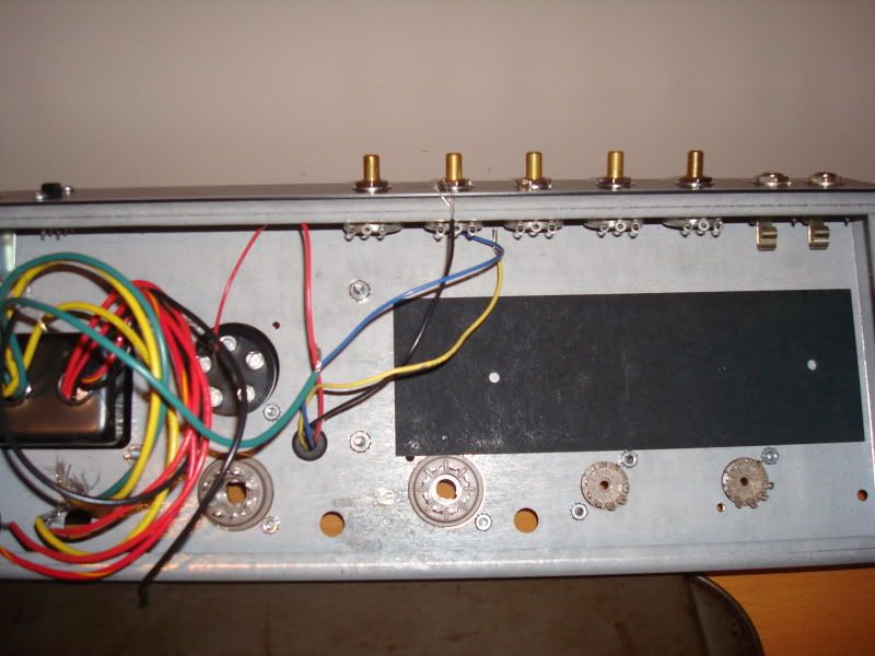
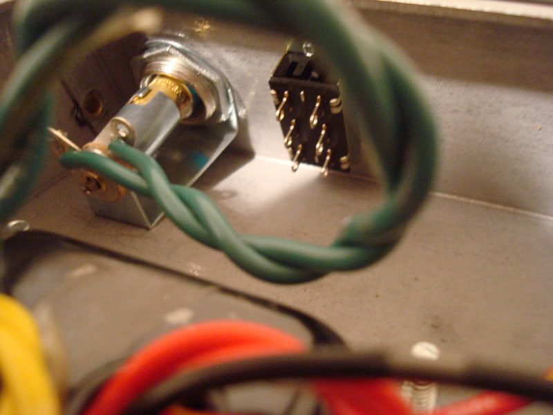
I hooked up the two 6.3 V green wires from the transformer to the light. So, do I run one wire to pin 2 and the other to pin 7 on the power tube or do I only run one wire to pin 2, and ground the other green wire?
I know they're supposed to hook up to the heaters on the preamp tubes as well, so I'm wondering if I can wire pin 2 on the power tube to the heaters on the preamp and just short pins 4 and 5?
Also, I'm not really sure where to wire the black wire to the on/off switch. It's got 6 different tabs at the back?? Can one of you guys shed some light on these minor issues?
Take a twisted pair of wire and go from the green filament wires on your 6.3v pilot light socket to the first power tube socket. Hook the wires to pin 2 and pin 7. Does not matter which wires goes to these two first pins. Do not solder them yet as you need to make another twisted pair of wires to go between your power tube sockets. Same thing but this time wire from pin 2 to pin 2. The other wire goes from pin 7 to pin 7.
It does not matter when going from your power tube to the preamp tube sockets which wire you use. But when you start on the preamp tube sockets you keep those preamp sockets in polarity going from pin 9 to pin 9 and pins 4/5 are together to pin 4/5 next preamp socket. Just trim off more wire from your twisted pair to go through both pins. Some people bend them together your choice.
You can use same color wire for both sides of your twisted pair or use black/green combo your choice.
Look at the Express layout in the Trainwreck files section that will show you how to wire the AC. But if you are trying to stay true to Fender then it will be different. Did Fender use that type of on/off switch?
Ok, so the light doesn't need to be grounded then?
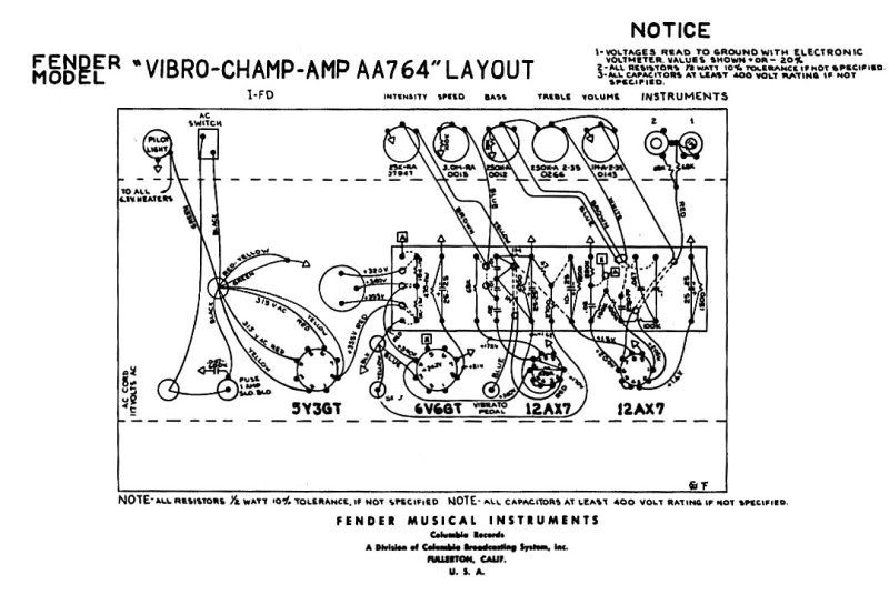
If you see the layout here, that's what's confusing me. One of the two 6.3 volt wires goes to the one of the ends at the back of the light holder, the other one does go to the second end at the back of the light as well but the first one gets wired to the heaters in the power tube but the other one just goes to ground after it passes the light.
Early Fenders run one heater wire to ground. The remaining wire goes to pin 2 on the octal and pins 4/5 on the novals. Pin 7 (octal) and pin 9 (noval) are grounded. Probably no harm in running a twisted pair, but Champs, Deluxes, Vibros, etc. were done "cheap and simple." If you do run a twisted pair, be sure to add 100R resistors from each wire to ground. Typically, this would be done right at the pilot light.
briane wrote:... it really is a journey, and you just can't farm out the battle wounds.
Note the light socket itself is grounded through the chassis when it is bolted on. Each of the green filament wires coming from the tranny has 3.15v so together they are 6.3v. We need both going to the light and then off to each power tube socket and each preamp tube socket.
Disregard that old Fender layout for now when doing the filament wiring.
Mark
Last edited by M Fowler on Sat May 09, 2009 4:58 am, edited 1 time in total.
Well if your intent is to go as stock as you can then following the grounding as shown on the Fender schematic and layout. But looking at your drilled front face plate area I assumed you were updating your circuit to more modern build.
EDITED
Sorry,
never mind I was looking at Norm's other layout when I was typing as I didn't realize there were two layouts until after I posted.
Mark
Normster wrote:Early Fenders run one heater wire to ground. The remaining wire goes to pin 2 on the octal and pins 4/5 on the novals. Pin 7 (octal) and pin 9 (noval) are grounded. Probably no harm in running a twisted pair, but Champs, Deluxes, Vibros, etc. were done "cheap and simple." If you do run a twisted pair, be sure to add 100R resistors from each wire to ground. Typically, this would be done right at the pilot light.
Awesome thx guys, but where do you place the resistors? At the pins?
Last edited by tribi9 on Sat May 09, 2009 5:28 am, edited 1 time in total.
