Hi people, I´d like to ask for your help/insight/experience on my build project, the D´luxe Princess. This is my first tube amp build, I have previously made a tube preamp, but that was on a PCB, so it doesn´t really count (...).
I got a set of transformers for a 5E3 Deluxe, so I went from there as a starting point, knowing that it would work well to power two 12AX7´s and two 6V6´s in PP. What I did was use the preamp section of the Princeton AA1164, removed the vibrato and reverb part, and "glued" it to the 5E3 Deluxe power amp. since I had a triode left, I added another gain stage with volume control. By the way, my target result sound wise is clean sound with humbuckers at low gain, and crunch/dist at high gain. Then I added some things such as an Fx loop, heater elevation, bleed resistor, middle control, screen resistors, changed rectification to diodes, feedback and an external speaker jack (this will be a combo).
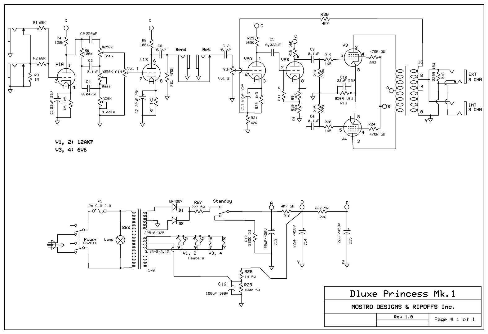
So I finished the schematic, here it is:
[IMG:3267:2241]http://i68.photobucket.com/albums/i5/Mo ... 1rev10.jpg[/img]
Later I´ll make the layout.
Now the questions:
1) First, will it work?? Have I missed anything basic?
2) Since I changed the rectification to diodes the voltages will be higher than with a recto tube, when I calculate the B+ after the diodes (325 x 1.4) it gives me 455V. I know that under load the voltage will drop some, but I think it´s too high for the 6V6´s, and also for the filtering caps, if I use 450V ones. I know that in Fenders the 6V6 is used above their specified plate voltage without problem (I think around 400V usually), but I don´t want to burn mine. So I put R27 after the diodes, to drop the B+, but I´m not sure what value should it have and what wattage rating. Anyone can help?
3) What do you think about the FX loop? Is that OK, design wise? I´m not sure about what the signal level and impedance will be at this point. Too high?
4) What about the heater elevation resistors, are they OK in value and wattage?
5) I upped the value of the feedback resistor, so as to get less feedback. will that work?
6) I added screen resistors for the 6V6´s although the 5E3 schem doesn´t have them. Will there be a problem with that?
7) What do you think about the speaker jacks connection? is it OK (the idea is that when you plug an external speaker, the internal one is disconnected)?
8) What do you think the result will be, sound wise? a "only dirt" amp? a clean machine?
Well, if there´s anything else you see that deserves comment, please do so. I know, it´s a lot of questions, but since this is my first build, I have zero experience, and that brings anxiety... I also know that some of my questions can be answered by doing the math, but I´m just learning about that, and usually my calculations end in total disaster...
Thanks for reading, for your time and your help.
Mostro
New amp project . Can you look at the schem?
Moderators: pompeiisneaks, Colossal
-
johnny riff

- Posts: 72
- Joined: Wed Aug 08, 2007 7:47 pm
- Location: N.H. USA
Re: New amp project . Can you look at the schem?
I think your B+ will be to high for cath.bias 6v6.and the 5e3 did not use FB.
JR
JR

Re: New amp project . Can you look at the schem?
Up to the FX loop is classic fender type circuit to change to pre-CBS you could run 33k at jacks not 68k, 110k instead of 100k plate resistor, 1.8k with 10mfd at cathode. The FX loop is a little different then I am used to but usually they have to be adjusted after the amp is built to change gain or add gain. Build a Dumblelator instead.
Re: New amp project . Can you look at the schem?
The PT is 325-0-325 using a full wave rectifier. Instead of R27 tied to the two uc4007 diodes it should to positive end of cap then to ground and to standby.
Re: New amp project . Can you look at the schem?
Isn't that power supply 650v = 325=0=325 secondary. 325v x .650 = 211.25v and each diode has drop of .7v so your voltage will be dropped.
can use 100mfd/350v cap and 10 ohm/10w resistor for filter stage. I would just use the standard Deluxe power schematic which is a rectifer tube.
Mark
can use 100mfd/350v cap and 10 ohm/10w resistor for filter stage. I would just use the standard Deluxe power schematic which is a rectifer tube.
Mark
Re: New amp project . Can you look at the schem?
Thanks people for your answers.
Johnny, yes, the feedback loop I added.
M Fowler, the Dumblelator is an external FX loop, right? Maybe next build...
I don´t quite get your last answer, where do you get the .650?
Johnny, yes, the feedback loop I added.
M Fowler, the Dumblelator is an external FX loop, right? Maybe next build...
I don´t quite get your last answer, where do you get the .650?

Re: New amp project . Can you look at the schem?
You may not require R27.
As an exercise why not plug values into Duncan's power supply calculator.
Providing you know PS transformer specs the results are surprisingly good.
(Note: in the calculator the source resistance of transformer for a full wave rectifier is half total resistance across the tranny, i.e. the resistance from centre tap to each arm).
You can also vary the current draw of 6V6s in the program to get a feel for effects of different operating conditions.
Re: New amp project . Can you look at the schem?
Thanks Ears, I,ve never used that program, I´ll take a look into it.
Meanwhile...
I´ve reworked the design.
[IMG 1494]http://i68.photobucket.com/albums/i5/Mo ... 1rev20.jpg[/img]
- Added a tube rectifier. I also added R27 and R30 to that, according to some things I read. Are they OK?
- Upped the first filter cap to 33 uF. Will it affect the recto tube?
- Eliminated the feedback loop. It will make the amp a bit more dirty, right?
- Added a switch to the third gain stage, the idea is to have more flexibility, from a "fender" type clean without the third gain stage to a more "marshally" JCM800 thing (I´m referring to the amount of distortion, not to the tone) with it in the circuit.
- Moved the FX loop´s location. I think here it will work better, at least in the sense of having more of the final sound at the send. If it´s not useful for interfacing with effects because of impedances and levels mismatch, at least I´ll have a preamp out and a power amp in...
Opinions?
Meanwhile...
I´ve reworked the design.
[IMG
 1494]http://i68.photobucket.com/albums/i5/Mo ... 1rev20.jpg[/img]
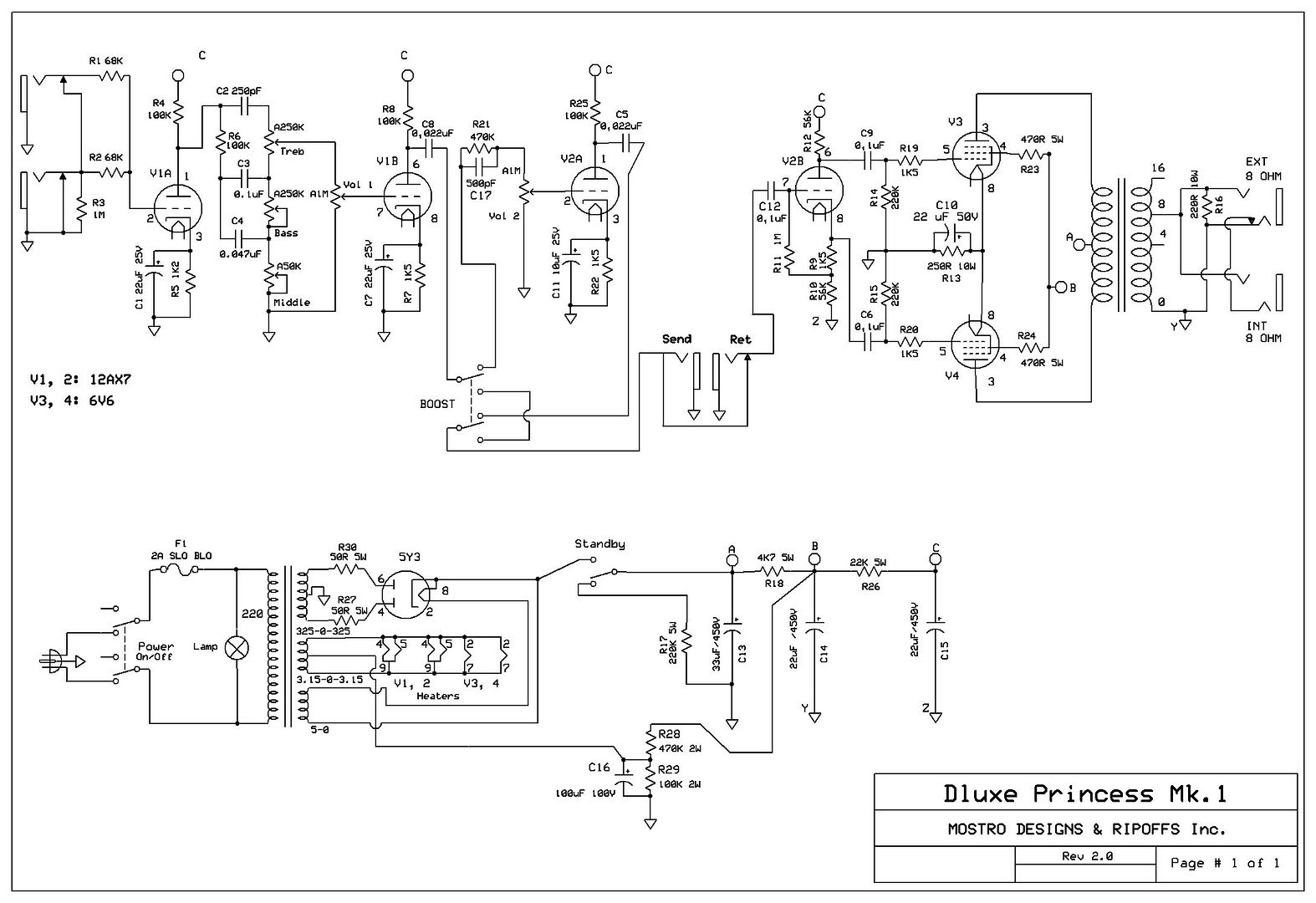
- Added a tube rectifier. I also added R27 and R30 to that, according to some things I read. Are they OK?
- Upped the first filter cap to 33 uF. Will it affect the recto tube?
- Eliminated the feedback loop. It will make the amp a bit more dirty, right?
- Added a switch to the third gain stage, the idea is to have more flexibility, from a "fender" type clean without the third gain stage to a more "marshally" JCM800 thing (I´m referring to the amount of distortion, not to the tone) with it in the circuit.
- Moved the FX loop´s location. I think here it will work better, at least in the sense of having more of the final sound at the send. If it´s not useful for interfacing with effects because of impedances and levels mismatch, at least I´ll have a preamp out and a power amp in...
Opinions?
Re: New amp project . Can you look at the schem?
If you visit http://www.valvewizard.co.uk/ you can find a couple of extremely simple mods to standby switching and heaters that you may think worth including.
Re: New amp project . Can you look at the schem?
Mostro, you probably meant to attach the top of your R17 to point "A". Regardless, there is still a bleed path through the heater center tap supply.
Re: New amp project . Can you look at the schem?
Ears, I´ve read those pages, anyway I´ll re-read them.
xk49w, actually I didn´t, I saw this kind of bleeder connection in the schem for the California Dreamer at AX84, but you´re right, I failed to see the path to ground through the heater center tap supply.
Thanks!
xk49w, actually I didn´t, I saw this kind of bleeder connection in the schem for the California Dreamer at AX84, but you´re right, I failed to see the path to ground through the heater center tap supply.
Thanks!
Re: New amp project . Can you look at the schem?
Here´s my latest schem revision, I changed the heaters reference, the bleeder cap, added R28, moved the R21 and C17 location. What do you think?
[IMG1494]http://i68.photobucket.com/albums/i5/Mo ... 1rev21.jpg[/img]
Thanks for reading.
[IMG
1494]http://i68.photobucket.com/albums/i5/Mo ... 1rev21.jpg[/img]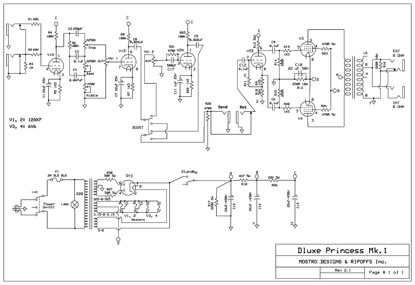
Thanks for reading.
Re: New amp project . Can you look at the schem?
Something about the input wiring doens't look quite right to me.
Tom
Don't let that smoke out!
Don't let that smoke out!