I'm still planning out a possible bump in B+ in a Marshall-style build, and I came across this thread: https://ampgarage.com/forum/viewtopic.php?t=36294
R.G.'s "redneck" solution in post #4 interested me since it might involve a cheaper solution to try out the higher B+ at a lower cost than committing to a new PT and an auxiliary PT would mean less power supply reworking than a complete PT swap. I'm specifically trying to raise B+ in my amp which uses a Heyboer Mojotone-spec JTM45 PT. With that setup it has 435V at the first node with 2x KT88 dissipating 50mA each at their cathodes. Nothing wild happening in the preamp aside from an added LFO for tremolo, so current draw there should be comparable to other 3x 12AX7 builds.
I like the transient response the amp has now, so I'm trying to add a small auxiliary PT to lift the existing PT that wouldn't dramatically increase the current capabilities of the power supply. The setup I'm thinking would have series rectifiers, though to keep the bias supply directly rather than capacitively coupled, it seems like reversing the order of the transformers would be sensible. In other words, rather than using the auxiliary PT to elevate the CT of the existing PT, I think I'd want to elevate the ground reference for a FWBR connected to the auxiliary PT. Using a small 10VA 34V toroidal (https://www.antekinc.com/an-0134-10va-34v-transformer/), the B+ should be elevated another 90V if the secondaries are wired in series for 68V. This is what I'm suggesting:
I'm posting primarily for a sanity check to ensure this is safe. The main thing that jumps to mind would be whether the auxiliary PT's insulation is capable of standing up to 435VDC above ground, though the datasheet says the dielectric strength is rated for 3500V between primary and secondary coils. However, this is unfamiliar territory for me, so I'm also trying to find out if there's a safety concern that hasn't occurred to me.
EDIT:
Re-reading the thread, I think R.G. is suggesting exactly this setup in his second post. Still, any safety concerns?
"Redneck" B+ lifter
Moderators: pompeiisneaks, Colossal
"Redneck" B+ lifter
You do not have the required permissions to view the files attached to this post.
-
martin manning

- Posts: 14308
- Joined: Sun Jul 06, 2008 12:43 am
- Location: 39°06' N 84°30' W
Re: "Redneck" B+ lifter
Mojo's 45 schematic shows 460V B+ with a GZ34 rectifier. Is your current rectifier a FWB?
Re: "Redneck" B+ lifter
No, it's currently set up with a FW rectifier. I suspect the difference is the increase in current demand with KT88 as compared to KT66. Assuming 70% dissipation, that Mojo schematic shows that PT supplying a total of 85mA at idle. With that said, I've measured mine idling between ~110-120mA which isn't that much more, especially considering the comparative bump in efficiency between diode and tube rectification. I briefly considered switching to a FWBR when I found this PT wasn't giving me the B+ I hoped for, but some quick math based on a read of the PT's datasheet has me concerned I'd get way more than I targeted: with B+ at 434VDC at approx 110mA, my PT is providing 307-0-307VAC. The datasheet specifies 350-0-350VAC at 200mA, which seems optimistic:

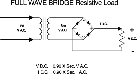
Taking 350VAC as my starting point (admittedly shaky ground) and using the voltage drop of 43VAC, I'm estimating the comparative current demand in light how a full-wave rectifier providing 1.0x current rating vs a FWBR providing 0.62x. So scaling 43VAC by 0.62^-1 gives 69.4VAC and a final secondary idle voltage estimate of 561VAC. With that math, I'm thinking B+ would be 789VDC with a capacitor input load. Admittedly with a resistive input load, that would work out to 544VDC, though I'm not aware of any resistor-input power supplies for guitar uses which gave me pause.
Between those, I thought a FWBR wouldn't be feasible, but there are admittedly a few assumptions behind the math result in some potentially error-ridden estimations.
EDIT:
I think an inductive input load would also provide B+ in a similar ~550VDC range with FWBR, but I wasn't sure if I'd need a larger inductor than the commonly available hash chokes. CE Dist sells a pretty inexpensive 250uH hash choke, but that seems like it might not be enough inductance to function as an inductive input load.
Last edited by cdemike on Fri Feb 28, 2025 1:14 pm, edited 1 time in total.
-
martin manning
- Posts: 14308
- Joined: Sun Jul 06, 2008 12:43 am
- Location: 39°06' N 84°30' W
1 others liked this
Re: "Redneck" B+ lifter
FWB is a no-go. You could just do this. Toroidal PT's commonly have two separate secondaries so it would be easy to temporarily connect one in. Bias voltage would increase in magnitude, which is fine. The auxiliary transformer should be rated for the same current as the main PT. Be aware that your load line will be more out of place for KT88 as you go to higher voltage keeping Va and Vg2 essentially the same.
You do not have the required permissions to view the files attached to this post.
Re: "Redneck" B+ lifter
I don't see how that can be correct, as it takes no account of the AC ripple current, required to boost the V DC up from the average towards the peak values of the rectified V AC.
Have you checked by measurement in your amp, or simulation (eg PSU2)?
https://www.justgiving.com/page/5-in-5-for-charlie This is my step son and his family. He is running 5 marathons in 5 days to support the research into STXBP1, the genetic condition my grandson Charlie has. Please consider supporting him!
Re: "Redneck" B+ lifter
Are you using a ss rectifier or a gz34? how about colder bias?
www.myspace.com/20bonesband
www.myspace.com/prostitutes
Express, Comet 60, Jtm45, jtm50, jmp50, 6g6b, vibroverb, champster, alessandro rottweiler
4x12" w/H75s
www.myspace.com/prostitutes
Express, Comet 60, Jtm45, jtm50, jmp50, 6g6b, vibroverb, champster, alessandro rottweiler
4x12" w/H75s
Re: "Redneck" B+ lifter
Thank y'all so much for your help with this!

Whereas the FWBR estimates came from these two:

It's certainly not elegant, but I'd want to try the amp like this for a while to see if I like it enough over time to justify the cost and work associated with a broader power supply overhaul. Any safety concerns (assuming a safe and secure wing job) if I kept it like that for a few weeks or months?
SS FW rectifier. Colder bias doesn't really impact B+ a ton, but my setup has a fairly narrow bias adjustment range (came up with my own to account for differences in what was in Marshall schematics and the potentiometers I had on-hand):
Yeah I'm almost certainly approaching this too simplistically. My math was based on an interpretation of the common Hammond rectifier guide, since under the scenario you mentioned I was comparing different rectifier setups with the same PT, so scaling things seemed to be a reasonable way to estimate it. But the 1x came from:
Whereas the FWBR estimates came from these two:
This this is great! Antek doesn't list the 34V transformer in the 10VA series datasheet, but playing with Watt's law to scale what current voltage and current would look under the load conditions described for other PT's that are there I noticed the magnitude of voltage drop for a given amount of current scaled well between the models, i.e., that each is fairly close to the 10W rating. Applying that information to the 34V transformer (again, another assumption), I get 147mA of current along each secondary at for the 34V. Scaling that in turn for an estimated 110mA current draw at idle, that transformer should be good for a 45VDC bump (likely an over-estimate considering the load line shift, as you mentioned). So that'd be pretty close to the rated current as the main PT.martin manning wrote: ↑Fri Feb 28, 2025 1:13 pm FWB is a no-go. You could just do this. Toroidal PT's commonly have two separate secondaries so it would be easy to temporarily connect one in. Bias voltage would increase in magnitude, which is fine. The auxiliary transformer should be rated for the same current as the main PT. Be aware that your load line will be more out of place for KT88 as you go to higher voltage keeping Va and Vg2 essentially the same.
It's certainly not elegant, but I'd want to try the amp like this for a while to see if I like it enough over time to justify the cost and work associated with a broader power supply overhaul. Any safety concerns (assuming a safe and secure wing job) if I kept it like that for a few weeks or months?
You do not have the required permissions to view the files attached to this post.
Re: "Redneck" B+ lifter
Your hand-drawn schematic has a rectifier that uses only 1/2 of the high-voltage secondary at any moment. The other half is disconnected by a reverse-biased diode.cdemike wrote: ↑Fri Feb 28, 2025 7:04 pm Yeah I'm almost certainly approaching this too simplistically. My math was based on an interpretation of the common Hammond rectifier guide, since under the scenario you mentioned I was comparing different rectifier setups with the same PT, so scaling things seemed to be a reasonable way to estimate it. But the 1x came from:
A full-wave bridge uses all of the high-voltage secondary, all the time.
If you mix the two approach without significant care, the center-tap of the high-voltage secondary will short-circuit your full-wave bridge and smoke the fuse (at least we hope it only burns a fuse).
Re: "Redneck" B+ lifter
1A slow-blow for the HT fuse should be replaced with 500mA
www.myspace.com/20bonesband
www.myspace.com/prostitutes
Express, Comet 60, Jtm45, jtm50, jmp50, 6g6b, vibroverb, champster, alessandro rottweiler
4x12" w/H75s
www.myspace.com/prostitutes
Express, Comet 60, Jtm45, jtm50, jmp50, 6g6b, vibroverb, champster, alessandro rottweiler
4x12" w/H75s
-
pdf64
- Posts: 2932
- Joined: Sat Mar 12, 2011 9:23 pm
- Location: Staffordshire, UK
- Contact:
1 others liked this
Re: "Redneck" B+ lifter
My perception is that Hammond rectifier document contains some dodgy info, it can't be used as a technical reference. Some of the equations are good, others seem made up up, perhaps a specific case being cited as universally true.cdemike wrote: ↑Fri Feb 28, 2025 7:04 pm ...
Yeah I'm almost certainly approaching this too simplistically. My math was based on an interpretation of the common Hammond rectifier guide, since under the scenario you mentioned I was comparing different rectifier setups with the same PT, so scaling things seemed to be a reasonable way to estimate it. But the 1x came from:
Whereas the FWBR estimates came from these two:
...
Generally the rms and peak voltage equations seem ok, current equations not so much.
eg it seems to me that for pretty much any given scenario, different values of reservoir cap will cause different levels of I AC.
Thoughts anyone? Could someone simulate it, PSU2 expert? @Martin Manning @Helmholtz
Last edited by pdf64 on Sat Mar 01, 2025 12:02 pm, edited 1 time in total.
https://www.justgiving.com/page/5-in-5-for-charlie This is my step son and his family. He is running 5 marathons in 5 days to support the research into STXBP1, the genetic condition my grandson Charlie has. Please consider supporting him!
-
martin manning
- Posts: 14308
- Joined: Sun Jul 06, 2008 12:43 am
- Location: 39°06' N 84°30' W
3 others liked this
Re: "Redneck" B+ lifter
Here you go. The transformers for FW and FWB would in reality have different cores and wire gauges.
You do not have the required permissions to view the files attached to this post.
Re: "Redneck" B+ lifter
so the FWB DC current is 0.71 x the AC secondary current, not 0.62?!
www.myspace.com/20bonesband
www.myspace.com/prostitutes
Express, Comet 60, Jtm45, jtm50, jmp50, 6g6b, vibroverb, champster, alessandro rottweiler
4x12" w/H75s
www.myspace.com/prostitutes
Express, Comet 60, Jtm45, jtm50, jmp50, 6g6b, vibroverb, champster, alessandro rottweiler
4x12" w/H75s
-
martin manning
- Posts: 14308
- Joined: Sun Jul 06, 2008 12:43 am
- Location: 39°06' N 84°30' W
1 others liked this
Re: "Redneck" B+ lifter
The Hammond sheet says (IDC/IAC])FWB/(IDC/IAC)FW is 0.62
Here we have (IDC/732)/(IDC/523), with the same IDC, leaving 523/732 = 0.714. Hammond may be considering the case where the same transformer is connected as a FWB vs. a FW, where the entire coil is used in FWB vs. just half of it at a time for a FW, which is the reference case.
Here we have (IDC/732)/(IDC/523), with the same IDC, leaving 523/732 = 0.714. Hammond may be considering the case where the same transformer is connected as a FWB vs. a FW, where the entire coil is used in FWB vs. just half of it at a time for a FW, which is the reference case.
Re: "Redneck" B+ lifter
The Hammond article has flaws.
The typical winding resistance of 50...100R per leg makes a huge difference; significantly lowers RMS winding current.
Using PSUD2 I'm getting Iac/idc ratios between 1.3 and 1.6.
The influence of the reservoir capacitance is rather weak.
It should be clear that the existing PT cannot be used with a bridge rectifier.
Boosting the transformer voltage will increase output power as well as PT current and might exceed the 200mA limit.
Re: "Redneck" B+ lifter
So the Idc/Iac ratio would then be 0.625-0.762.
Basically, Hammond seems to err on the low side
www.myspace.com/20bonesband
www.myspace.com/prostitutes
Express, Comet 60, Jtm45, jtm50, jmp50, 6g6b, vibroverb, champster, alessandro rottweiler
4x12" w/H75s
www.myspace.com/prostitutes
Express, Comet 60, Jtm45, jtm50, jmp50, 6g6b, vibroverb, champster, alessandro rottweiler
4x12" w/H75s