I am trying to rewire the power supply on an old Ampeg G15 that someone disassembled and left abandoned some time ago.
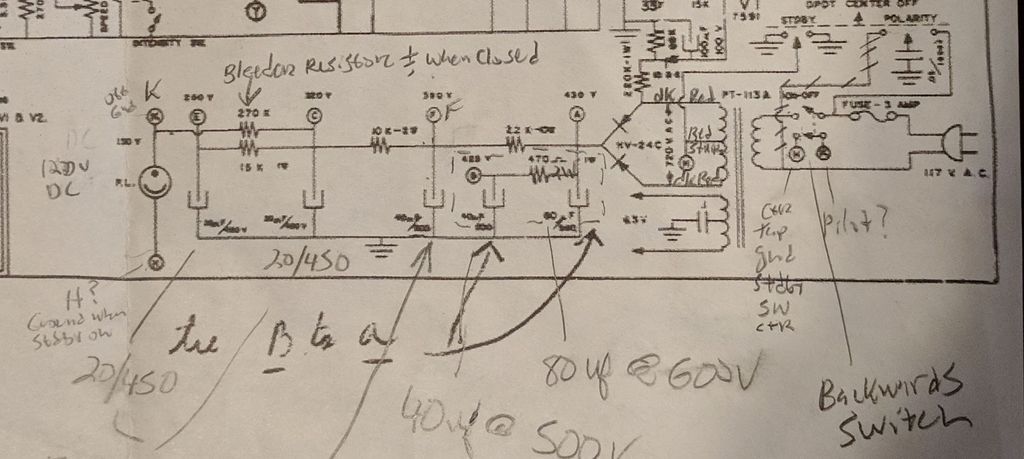
My question is about the way the pilot light was originally wired. Looks like it runs off of DC from the 270K resistor at point "K".
Seems that 1/2 of the power switch was used to short across the pilot lamp to use the 270k resistor as a "bleeder" when the amp power switch was in the off position. Note the poles of the power switch are "backwards" from one another - meaning when the switch that powers the primary with 120V is closed, the other leg of the switch with the indicator is open.
Questions:
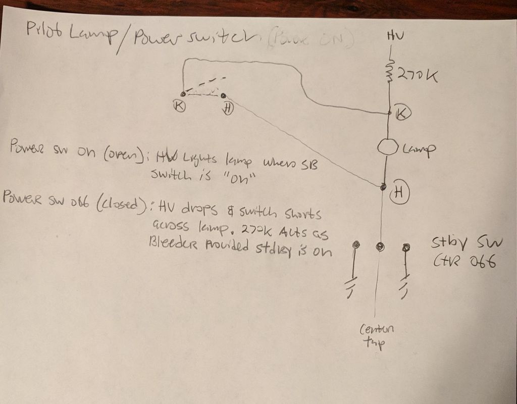
Is my hand-drawn "simplified version" correct?
If so, when the standby switch is in the center "off" position, how would the pilot light stay on?
Your drawing is correct. The pilot lamp operates anytime the power switch is on. It is independent of the STBY/POL switch positions because the lamp is connected directly to the PT center tap.
The contacts on the power switch that short across the lamp simply kill the lamp immediately when power is switched off. Without those contacts, the pilot would stay on for a while until the filter caps drained after turning power switch off.
I have the same situation as 65greg. a 66 Ampeg G15 that someone had really messed up the wiring. Having trouble wrapping my head around the solution, mainly as it pertains to the wiring of the hardware. Could someone please indicate the actual wiring hookups by filling in the wiring diagram I"ve attached. (sluckey?) I'm installing a 3 prong cord and want to use the original switches (see pic) but eliminate the polarity function. Is there a way to hook up the DPDT switch so that it only yields the + polarity no matter the position? The amp currently has a purple wire from the pilot light at "K" and a black wire from the pilot light at "H" that each go to the switches.
Thanks for any help.
Tom
You do not have the required permissions to view the files attached to this post.
Stevem wrote: ↑Sun Dec 04, 2022 5:28 pm
While your in there working on that G15 I would increase that 2.2K power supply dropping resistor to a 15 watt.
According to the schematic there is 40VDC across that 2.2K. That means that resistor is only dissipating .73 watts. I would expect the stock 10 watt resistor handles that just fine.
i hear you, sluckey, but I'm still not sure how the wiring goes. Can you download my wiring diagram and do a layout? Or should I just fill it in myself and post it for approval? I'm mainly confused as to where the purple wire connects and also the center tap (same place?). I was planning on attaching the neutral (white) to the primary at he 1st hole on the eyelet board, and not having it connect to the DPDT at all.
Thanks Steven, but I don't know how the switch is wired. What wires connect to it? and from where they originate. Maybe you could reference my diagram and describe the connections. i apologize for my limited understanding.
Before you get in too deep here do you even know if the power transformer is good?, as I wonder why this amp was discarded.
I have seen a lot of the power transformers short out and the output transformers go open on one side in these amps over the years!
I would scroll back up to near the top in this tech section and read the "Blowing fuses/ debugging" post first.
When I die, I want to go like my Grandfather did, peacefully in his sleep.
Not screaming like the passengers in his car!
Cutting out a man's tongue does not mean he’s a liar, but it does show that you fear the truth he might speak about you!
Steven,
The power transformer is good. The previous owner tried to do some tinkering and had the screen grids of the 7591 output tubes connected at pin 4 to the filter cap and at pin 8 to ground. It burned up the 470 ohm resistor. He also had the cathode pin 5 connected where the control grid should connect. Once I saw all that I was leery of what else he might have done so I disconnected the wiring to the power supply section and began my quest to hook it up again, correctly. Sadly, the guy passed away recently and his family is trying to assess the value of all the gear he had and it's a lot of nice gear. i already tuned up a Kendrick 2410 (bassman copy) as well as a couple of small "harp" amps. The pilot light I expected to see the usual 6.3 volt set up and was thrown by the one in there and the way it is wired. I installed a new cap can 80/40/40 and a new 470ohm resistor, have new matched 7591s and am installing a 3 prong cord.
Thanks again for sharing your knowledge.
Tom
I've been watching this thread, mostly because it strikes a nerve with me. I dislike switch wiring because, inevitably, anything more complicated that a simple on-off, single or double throw baffles me. In addition, there is no need for half of the stuff that's in the switch wiring shown on the schematic. I believe we know a whole lot more now about guitar amp power supplies than we used to. I think you are working overtime to do something that will yield no benefit.
First point is that the standby isn't needed. Neither is the polarity switch. Just detach everything from them and leave the switches there doing nothing. You'll need to ground (H) as that is connected to the high voltage center tap. Use the same ground as the cap for node A. That gets rid of all sorts of complications.
Second point is that you can also simplify the power switch now that the standby is out of the circuit. Do this:
120VAC hot lead (usually black) > fuse > power switch > power transformer primary. The switch makes/breaks the connection between the fuse (and thus the hot voltage supply) and the PT primary.
120VAC neutral (usually white) > other transformer primary. If the power switch is double pole and you want to make/break the hot and neutral at the same time, you can bring the white/neutral to the #2 side of the switch and the other PT primary to the #2 side of the switch.
Wire the pilot light parallel to the PT primary -- the same connection points on the switch for the PT primary leads.
The power switch is a simple on/off switch with two poles. This double pole, single throw or DPST. 120VAC supply goes to the top pair of poles. PT primary and pilot go the to bottom half. Easy-peasy.
Now, your amp is wired to 21st century standards and you are done. No fuss.