Just saying hello to Wild Bill..........................
I will check that canadian site,thanks for the link.
Take care
Aharon
Choke primer
Moderators: pompeiisneaks, Colossal
Re: Choke primer
Hope, my adviced were helpful at that time!Wild Bill wrote:"Vee Gates?" my friend! It's been a while! I was thinking of you these past few days. I've got another Dclone on the go and I had printed out some advice you had given me some time ago.
I haven't dealed anymore with building Dumble clones since the late 90', because I then went completely on the 'British Sound Way'. I have designed a completely new amp in the early 2000', the 'British Purist' - have completely over-worked my DINO concept and due to lots of backorders never again had the time until now, to engage myself again with dumble-ish concepts...
... but after hearing some incredible sounding clips of some Dumble clones here on this place recently, I was re-infected again with this darn Dumble virus! Shit!
Now I have a D'Lite44 from BrownNote (hopefully) soon on its way across the pond to me, a Dumble clone w/ 4 x 6V6 in the power stage, alternatively there may be set 2 x 6L6, to quite my desire after this sweet, nice guitar sounds and playing feel
When you're furthermore on the dumble-ish way, then here's the best place at all for you! This board has some very helpful people with huge knowledge and experience concerning Dumble & TRW designs, that it's really fun and satisfaction, to be here!
Well, this shows your tastefulnessWild Bill wrote:Still drinking Spaten Pils once in a while!
Enjoy this board and have fun! Hope to see you posting furthermore!
Larry
Larry's Website now with included Pix's Gallery

Re: Choke primer
This thread goes back a bit and started with a question about choke values. Mark's post above mentions low freq oscillation with LC filters in power supply.mhuss wrote:The main reasons for not using a choke (from a manufacturer's point of view) are expense and weight, not any technical reason.
It is instructive to watch B+ of both types under load with a 'scope. The RC type have very regular (and fairly large) 100 or 120hz ripple, while the LC type look smooth on first glance, but are actually sloshing up and down at a very low and irregular frequency.
This latter is way too low to be heard (or passed through an OT), so the audible difference is less hum coming out of the speaker when using a choke, particularly with SE amps.
--mark
Now I've worked through a web page cookbook style PS design proceedure by http://www.turneraudio.com.au/powersupplies.html and found it very informative. It's hi fi and so I assume, fairly exacting. At one point (when determining values for L) he/we calculate the power supply resonance and he opines that anything below 7Hz is acceptable.
My question is related to this and ghost notes, which according to http://www.valvewizard.co.uk/ (Smoothing and Filtering the Power Supply) are due to high values of reservoire capacitance. What causes the ghost notes ? Hi Fi guys often seem to be happy with reservoire caps in excess of 180uF, but we seldom see that in instrument amps. Are these so called ghost notes actually due to power supply resonance?
I suspect (happy to be wrong) that ghost notes are not wholly dependant on the reservoire cap but on the LC combination.
By the way I had a query (I think in this thread) re fly back voltage spikes from chokes when taking B+ for a SE after a CLC filter that no one seemed to be able help me with. Answer: well don't do it, not if you incorporate the usual Stby arangement.
Edit: Because of LOUDthump (heh, heh) when switching from run to standby.
Last edited by Ears on Wed Jan 02, 2008 9:44 am, edited 1 time in total.
Re: Choke primer
I've heard off note modulation with too *low* a filter value, but not with too high. This term usually refers to modulation caused by excessive PS ripple (due to undersized filters).
Just thinking out loud, if too high were a problem the audio freaks wouldn't use large values, as they tend to be highly sensitive and attuned to unwanted distortion.
--mark
Just thinking out loud, if too high were a problem the audio freaks wouldn't use large values, as they tend to be highly sensitive and attuned to unwanted distortion.
--mark
Re: Choke primer
Exactly my thoughts, but how to explain this (from the valve wizard site);mhuss wrote:I've heard off note modulation with too *low* a filter value, but not with too high. This term usually refers to modulation caused by excessive PS ripple (due to undersized filters).
Just thinking out loud, if too high were a problem the audio freaks wouldn't use large values, as they tend to be highly sensitive and attuned to unwanted distortion.
--mark
Choosing the reservoir capacitor (you can cut to chase by skipping to the last paragraph):
"One reservoir capacitor cannot smooth all the ripple voltage (unless it were infinitely large), so we must decide how much HT ripple voltage we can tolerate and choose a capacitor that can achieve it.
The ripple voltage is expressed as a percentage of the total HT voltage, so a 100Vdc HT with a 10V peak-to-peak ripple 'riding' on it has 10% ripple.
Push-pull amps can tolerate more HT ripple because they cancel common mode noise. We could reasonably allow as much as 20% ripple voltage, and 10% would be excellent.
Single-ended amps are more susceptible to HT ripple, so we would allow 10% at most, and 5% would be better. Adding a second filter before the power valve is sometimes done in single-ended amps, bringing the ripple voltage down to a very low level. This is not so easy in high power amplifiers as they draw significant current and we would need a very large power resistor or choke in the filter.
In the following example we have a 50W push-pull amp, and the HT after rectification is 350Vdc. We also need to know the average current the amp will draw. This will be the sum of the quiescent currents of all the valves.
Supposing this amp has two ECC81's, an EF86 and two EL34's, the average current drawn by each triode will be about 5mA and there are four triodes in all, making 20mA. The EF86 will draw about 3mA, making 23mA for the pre-amp.
We will assume that the power valves are biased to their maximum dissipation of 25W each (if the amp is Class-AB they won't be biased that hot, but we should assume worst case scenario). The average anode current they draw will be in the region of:
I = P / V
I = 50 / 350
= 143mA.
The screen-grids will also draw a quiescent current: The data sheet for the EL34 suggests a screen-to-anode current ratio of 6.5, so we can expect the screen currents to sum to:
143 / 6.5 = 22mA.
Added to the pre-amp current this makes 188mA in total for the whole amplifier. (Remember, this is the average current, and is not the same as the peak current that the amp will draw. In an amp like this, depending on the class of operation, the peak current might be 200mA for one EL34 (while the other EL34 goes into cut-off) plus the 23mA pre-amp current which won't vary much. That makes 223mA peak, and the power transformer would need to be rated for at least this amount.)
We decide to allow 10% ripple. The HT is 350V, so 10% of this is:
(350 / 100) * 10 = 35Vp-p.
The reservoir capacitor can be found using:
C = (t * I) / V
Where:
I = average load current drawn
V = ripple voltage peak-to-peak
t = duration between charging cycles and is equal to: 1/mains frequency.
In Europe the mains frequency is 50Hz, so: t = 1/50 = 0.01 seconds.
The reservoir capacitor required will be:
C = (0.01 * 0.188) / 35
= 54uF.
The nearest standard is 47uF. This would give a 40V ripple which is 11%; perfectly adequate. Most modern designs use a value from 33uF to 100uF at most. If using a valve rectifier you MUST check the data sheet to see if the value of capacitor is allowable [see below]. Beware also that unecessarily large amounts of smoothing / filtering can lead to 'ghost notes'- an unwanted effect where a vague, fuzzy echo follows each note played.
-
gregarious
- Posts: 49
- Joined: Mon May 08, 2006 11:21 am
Re: Choke primer
Thanks for all the responses, it's always surprising how different perspectives on the same theme contribute to better understanding.
Here's a page which may be helpful
http://www.turneraudio.com.au/audiofilterchokes.html
Here's a page which may be helpful
http://www.turneraudio.com.au/audiofilterchokes.html

Re: Choke primer
Hi all,
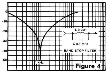
Do anybody put a little cap in parallel with the choke to obtain resonance at the ripple frequency? (eg 60Hz or 120Hz FullBridge in USA and 50/100Hz in Europe)
Do anybody put a little cap in parallel with the choke to obtain resonance at the ripple frequency? (eg 60Hz or 120Hz FullBridge in USA and 50/100Hz in Europe)
Re: Choke primer
And what's the benefit?roberto wrote:Do anybody put a little cap in parallel with the choke to obtain resonance at the ripple frequency?
Larry
Larry's Website now with included Pix's Gallery
-
Andy Le Blanc
- Posts: 2582
- Joined: Sat Dec 22, 2007 1:16 am
- Location: central Maine
cap in parallel with the choke to obtain resonance
the benefit is that you form a LC trap circuit centered at the ripple frequency...resonating the choke and reducing ripple voltage.... theres a formula... but its tricky in practice..... a lot of variables so you have to fiddle with it..... but its useable
lazymaryamps
Re: Choke primer
Exactly. The formula is: f = 1 / [2 * pi (sqrt LC)] or, if you want to try on an amp already build, the capacitance is: C = 1 / [L * (2 * pi * f)^2]
EG for a 100Hz full rectified and 10H inductance, you need 253nF. Is it better to start with 220n and then add some smaller caps in parallel to obtain the best result (not only 33n, but maybe 22 or 47n give you better results).
If you want to make it simpler, that's the way (C in nF, L in H):
50Hz --> C = 10132 / L
60Hz --> C = 7036 / L
100Hz --> C = 2533 / L
120Hz --> C = 1759 / L
Happy new year!
Re: Choke primer
Serendipity, I came on this picture searching something else:
[img:446:302]http://www.ethanwiner.com/filter-4.jpg[/img]
Just to explain better what I use it for.
[img:446:302]http://www.ethanwiner.com/filter-4.jpg[/img]
Just to explain better what I use it for.
Re: Choke primer
Didn't read whole thread. Ignore this post.
-
iknowjohnny
- Posts: 1070
- Joined: Thu Apr 24, 2008 2:10 am
- Location: los angeles
Re: Choke primer
heres a question i have wondered since i first built the amp I always ask questions about here. When i built it i intended the PA to be close to a matchless chieftain which has a 20H choke. So thats what i used. At the time i wasn't aware how unusual that was nor that i would eventually end up with a more traditional marshall style PA. So i have long wondered what the result is of using a 20H choke when a 3 would be more typical. can anyone explain to me the tonal differences? I did try a smaller one (around 4H i think) out of a fender long ago and recall not liking it as much, but the amp was very different and has since evolved into a much different one. So what would i hear/feel if i stuck a smaller choke typical of marshalls in it?
Re: Choke primer
It depends also on Rdc of the choke.
Usually higher chokes make the amp sound stiff,with an hard low end.
Smaller chokes with higher Rdc make the amp sound more loose,
softer low end and with a "midrangey feel".
Usually higher chokes make the amp sound stiff,with an hard low end.
Smaller chokes with higher Rdc make the amp sound more loose,
softer low end and with a "midrangey feel".
-
iknowjohnny
- Posts: 1070
- Joined: Thu Apr 24, 2008 2:10 am
- Location: los angeles
Re: Choke primer
"midrangy feel"......that sounds like what i'm missing, tho not high mids but lower mids in the 500-700Hz range. If it would have more of that i'd definately make a change. What is rdc? You mean the voltage max? Mine is a hammond 193C 20H/100ma. Not sure about the V but i know it's conservative.
Last edited by iknowjohnny on Sun Feb 21, 2010 4:38 pm, edited 1 time in total.