Will do.martin manning wrote:It's cathode biased, which will reduce the output. The pentode-triode switch is the usual type where both screens are connected to the anode (not to ground!). Measure that OT again.
50W Plexi, Dual Rectifier, PPIMV Budget Build
Moderators: pompeiisneaks, Colossal
Re: 50W Plexi, Dual Rectifier, PPIMV Budget Build
Re: 50W Plexi, Dual Rectifier, PPIMV Budget Build
Thanks!JazzGuitarGimp wrote: I imagine so. Nice work!
Is the 442 a Digidesign interface?
Yep. It's from an old Avid Media Composer 1000. We took it out of service many years ago and I stashed the 1U boxes for some future project. Never imagined it would be a tube amp.
Peace,
Mark
Re: 50W Plexi, Dual Rectifier, PPIMV Budget Build
Well here's a lesson in not believing ratings.
The 9v wall wart measured 11.5v when connected to the OT 8Ω tap. 277v on the primary.
24:1 ratio
24*24=576
576*8=4600 4.6K
Peace,
Mark
The 9v wall wart measured 11.5v when connected to the OT 8Ω tap. 277v on the primary.
24:1 ratio
24*24=576
576*8=4600 4.6K
Peace,
Mark
-
martin manning

- Posts: 14308
- Joined: Sun Jul 06, 2008 12:43 am
- Location: 39°06' N 84°30' W
Re: 50W Plexi, Dual Rectifier, PPIMV Budget Build
That's more like it. If you wanted a more accurate answer yet, you could put an 8-ohm resistor on the 8-ohm tap and put the AC signal into the primary.
Re: 50W Plexi, Dual Rectifier, PPIMV Budget Build
The salt & pepper grill cloth that I have isn't going to work out. So, in the spirit of staying on budget...which there is none...I decide to look at using some black cloth that I have. Input appreciated.
First, just a change from s&p to black.
[IMG 768]http://www.crenshawweb.com/plexi50/cab4.jpg[/img]
Then, the same but with white piping across the top of the bezel.
[IMG768]http://www.crenshawweb.com/plexi50/cab5.jpg[/img]
With black piping...if they even make such a thing.
[IMG768]http://www.crenshawweb.com/plexi50/cab7.jpg[/img]
Then, black on black. Looks unfinished to me but there's a certain vibe about it.
[IMG768]http://www.crenshawweb.com/plexi50/cab6.jpg[/img]
Peace,
Mark
First, just a change from s&p to black.
[IMG
 768]http://www.crenshawweb.com/plexi50/cab4.jpg[/img]
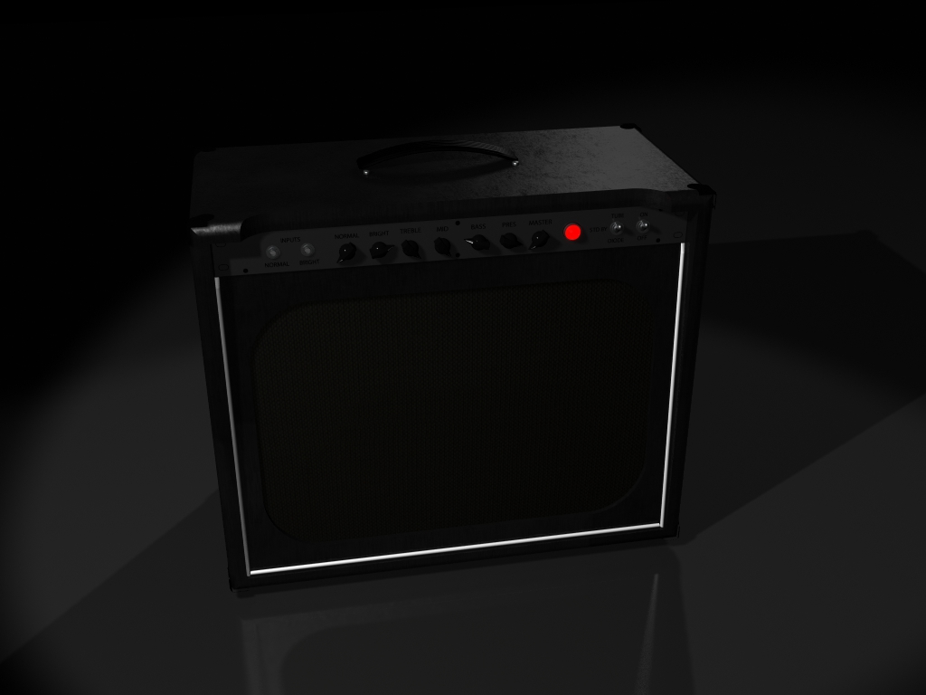
Then, the same but with white piping across the top of the bezel.
[IMG
768]http://www.crenshawweb.com/plexi50/cab5.jpg[/img]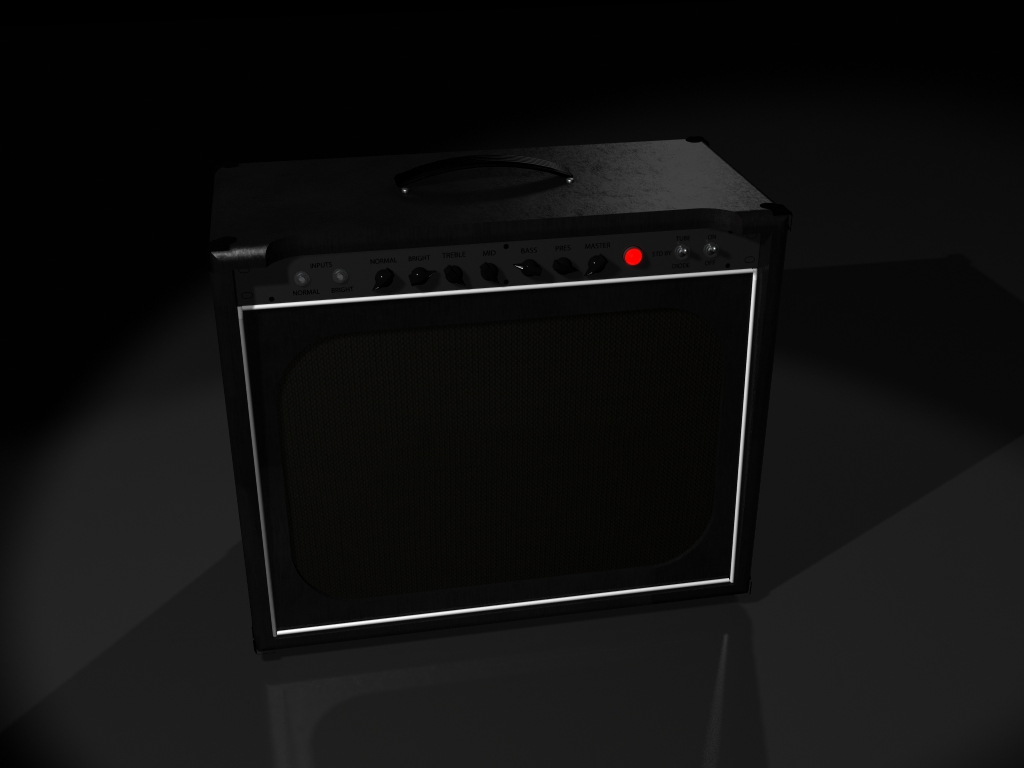
With black piping...if they even make such a thing.
[IMG
768]http://www.crenshawweb.com/plexi50/cab7.jpg[/img]
Then, black on black. Looks unfinished to me but there's a certain vibe about it.
[IMG
768]http://www.crenshawweb.com/plexi50/cab6.jpg[/img]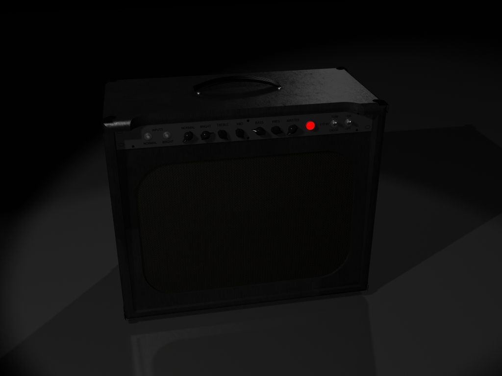
Peace,
Mark
Re: 50W Plexi, Dual Rectifier, PPIMV Budget Build
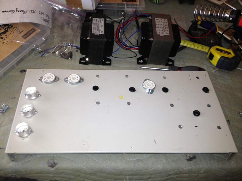
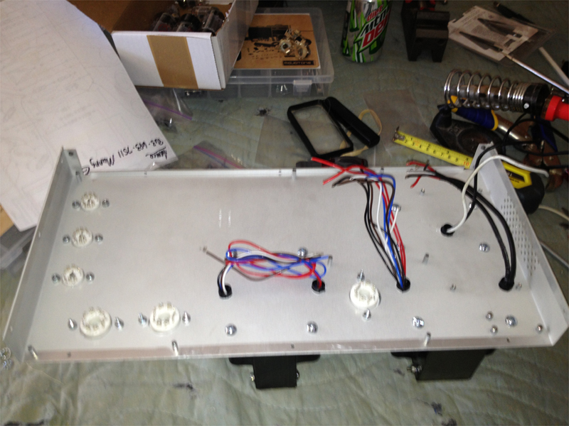
More progress on the chassis. Actually, I took a few steps backward and drilled the other 1U bottom. I had made a few mistakes on the wiring holes and had to re-drill and it just got messy. I'm much happier with this effort. Practice made the difference.
Sorry for the blurry pics. My iPhone just refuses to hold focus. I get some better shots when I'll get my camera battery charged.
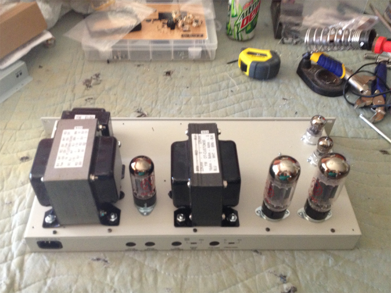
I did a test fit of all the components so I could check hole position and figure out where the board will live.
[IMG:800:600]http://www.crenshawweb.com/plexi50/build28.jpg[/img]
[IMG:800:600]http://www.crenshawweb.com/plexi50/build29.jpg[/img]
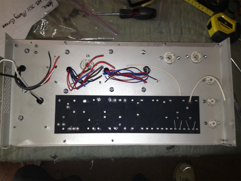
To keep everything in close proximity and all attached to one half of the chassis, the board will mount right side up but will be attached to the same half. Meaning component side against the case. Plenty of room left for filter caps.
[IMG:800:600]http://www.crenshawweb.com/plexi50/build30.jpg[/img]
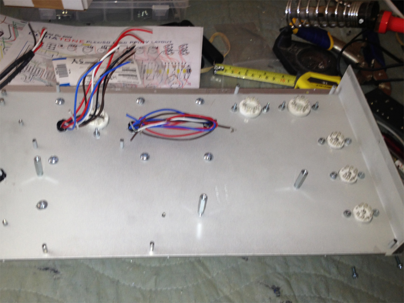
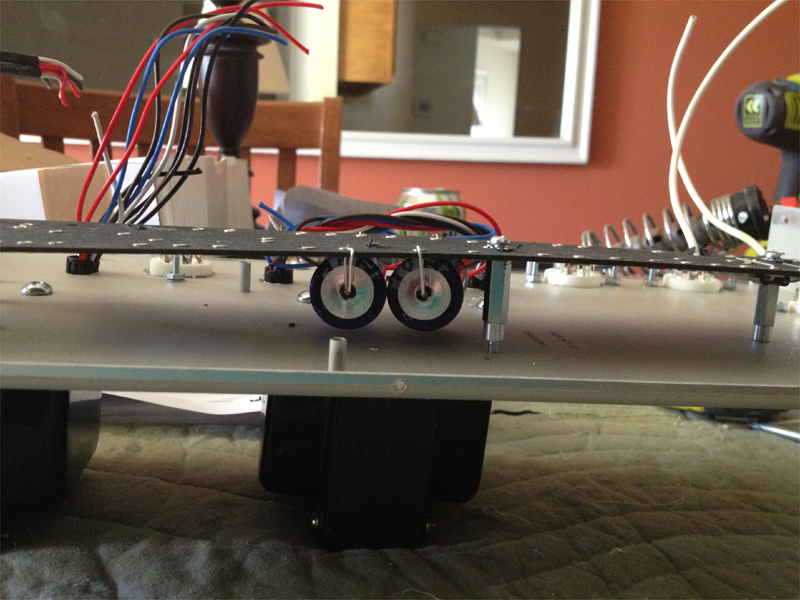
Standoffs that I salvaged from some computer cases will give the room I need to clear the 47uf caps on the board. These are by far the tallest components.
[IMG:800:600]http://www.crenshawweb.com/plexi50/build31.jpg[/img]
[IMG:800:600]http://www.crenshawweb.com/plexi50/build32.jpg[/img]
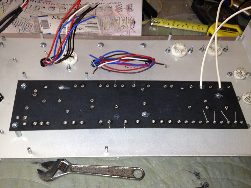
Plenty of clearance...even when I get that front standoff tightened down...missed that one.
[IMG:800:600]http://www.crenshawweb.com/plexi50/build33.jpg[/img]
All buttoned up, test fit complete.
[IMG:800:600]http://www.crenshawweb.com/plexi50/build34.jpg[/img]
[IMG:800:600]http://www.crenshawweb.com/plexi50/build35.jpg[/img]
Sorry for the blurry pics. My iPhone just refuses to hold focus. I get some better shots when I'll get my camera battery charged.
I did a test fit of all the components so I could check hole position and figure out where the board will live.
[IMG:800:600]http://www.crenshawweb.com/plexi50/build28.jpg[/img]
[IMG:800:600]http://www.crenshawweb.com/plexi50/build29.jpg[/img]
To keep everything in close proximity and all attached to one half of the chassis, the board will mount right side up but will be attached to the same half. Meaning component side against the case. Plenty of room left for filter caps.
[IMG:800:600]http://www.crenshawweb.com/plexi50/build30.jpg[/img]
Standoffs that I salvaged from some computer cases will give the room I need to clear the 47uf caps on the board. These are by far the tallest components.
[IMG:800:600]http://www.crenshawweb.com/plexi50/build31.jpg[/img]
[IMG:800:600]http://www.crenshawweb.com/plexi50/build32.jpg[/img]
Plenty of clearance...even when I get that front standoff tightened down...missed that one.
[IMG:800:600]http://www.crenshawweb.com/plexi50/build33.jpg[/img]
All buttoned up, test fit complete.
[IMG:800:600]http://www.crenshawweb.com/plexi50/build34.jpg[/img]
[IMG:800:600]http://www.crenshawweb.com/plexi50/build35.jpg[/img]
-
martin manning
- Posts: 14308
- Joined: Sun Jul 06, 2008 12:43 am
- Location: 39°06' N 84°30' W
Re: 50W Plexi, Dual Rectifier, PPIMV Budget Build
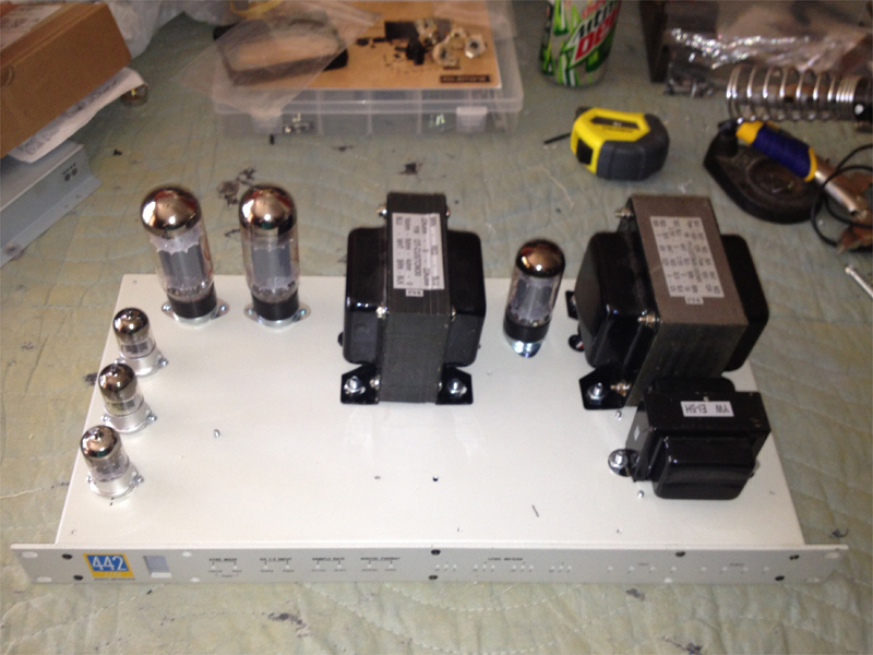
I think I would rather have the components on the top side of the board for better accessibility. I notice that you had the PT and OT laminations at 90-degrees to one another the first time, which is usually better for minimizing magnetic coupling. Did you listen to the OT with the PT energized to see if there is any issue there?
Re: 50W Plexi, Dual Rectifier, PPIMV Budget Build
I agree. Having access would be nice. I guess I could solder to the back side of the eyelets but that would mean building the layout in reverse...probably an exercise in frustration for only my second build. I'll have to think about this one.martin manning wrote:I think I would rather have the components on the top side of the board for better accessibility. I notice that you had the PT and OT laminations at 90-degrees to one another the first time, which is usually better for minimizing magnetic coupling. Did you listen to the OT with the PT energized to see if there is any issue there?
Transformer placement. Yep, I screwed that up. I'd almost rather re-drill it than mess with a live PT. If I were to check them, what would I be listening for?
Peace,
Mark
Re: 50W Plexi, Dual Rectifier, PPIMV Budget Build
After thinking about this for a few minutes, mounting the board upside down would be more of a problem than just access. If I needed to re-flow a joint to add a lead, I could see resistor and capacitor leads falling out of position. Darn gravity.martin manning wrote:I think I would rather have the components on the top side of the board for better accessibility.
Looks like I'll be building the layout in reverse. I should probably print in out reversed so I at least have a road map that matches.
You're always making me think Martin. I appreciate your input and experience. You see things at a glance that would take me hours of frustration to figure out.
Peace,
Mark
-
martin manning
- Posts: 14308
- Joined: Sun Jul 06, 2008 12:43 am
- Location: 39°06' N 84°30' W
Re: 50W Plexi, Dual Rectifier, PPIMV Budget Build
It's pretty simple to check for coupling. First put the bare ends of all the PT secondary leads between two strips of blue painter's tape, spaced about 1/2-3/4" apart. Then put line voltage on the PT primary and measure the AC voltage on the OT secondary. Ideally it would be zero, but if it's only a mV or two it is all good. If it's more than that, you can listen to it and see what kind of volume the hum has by connecting the speaker.
I often use reversed printouts for one thing or another... damned convenient!
I often use reversed printouts for one thing or another... damned convenient!
Re: 50W Plexi, Dual Rectifier, PPIMV Budget Build
Thanks Martin. I'll give it a try.martin manning wrote:It's pretty simple to check for coupling. First put the bare ends of all the PT secondary leads between two strips of blue painter's tape, spaced about 1/2-3/4" apart. Then put line voltage on the PT primary and measure the AC voltage on the OT secondary. Ideally it would be zero, but if it's only a mV or two it is all good. If it's more than that, you can listen to it and see what kind of volume the hum has by connecting the speaker.
I often use reversed printouts for one thing or another... damned convenient!
Reversing the layout works great for components on the board but I have to remember all the sockets, jacks and pots are still oriented correctly.,,opposite what the printout shows. I'm going to add text reminders to the layout before I print. This will be slow going for sure.
Peace,
Mark
Re: 50W Plexi, Dual Rectifier, PPIMV Budget Build
Martin,
Did you see my question early on about removing two of the inputs? I want to have a Normal and Bright hi Z and lose the low Z jacks. Do I just remove the other 68K mix resistors?
I remember from checking the inputs on my Bassman that the junction of those Rs played a role in metering so I'm not sure if removing them will cause a ripple effect somewhere in the circuit.
I'm going to machine the new face plate today and need some clarification on this mod.
Peace,
Mark
Re: 50W Plexi, Dual Rectifier, PPIMV Budget Build
I realized I hadn't given much thought to the PT primary hook up. There are two bundles of wires, both colored coded the same. I checked the schematic and this is what I believe is correct for 120V hook up...the heavy black and red lines on the pic. Can someone verify this for me? The link is a higher res version.
http://www.crenshawweb.com/plexi50/pt_primary_hi.jpg
[IMG 500]http://www.crenshawweb.com/plexi50/pt_primary_lo.jpg[/img]
http://www.crenshawweb.com/plexi50/pt_primary_hi.jpg
[IMG
 500]http://www.crenshawweb.com/plexi50/pt_primary_lo.jpg[/img]
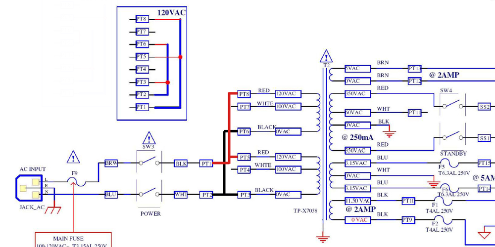
-
martin manning
- Posts: 14308
- Joined: Sun Jul 06, 2008 12:43 am
- Location: 39°06' N 84°30' W
Re: 50W Plexi, Dual Rectifier, PPIMV Budget Build
Hook up the PT primary exactly as shown in the schematic, paralleling the two 120VAC windings. Observe the colors so that the phase relationship is correct.
On the inputs, yes keep the 1M at the jacks from tip to ground, tie the switching contact to ground (so the inputs are shorted to ground when no plug is inserted), and then take each tip through a single 68k on the way to the grids.
On the inputs, yes keep the 1M at the jacks from tip to ground, tie the switching contact to ground (so the inputs are shorted to ground when no plug is inserted), and then take each tip through a single 68k on the way to the grids.
Re: 50W Plexi, Dual Rectifier, PPIMV Budget Build
Thanks!martin manning wrote:Hook up the PT primary exactly as shown in the schematic, paralleling the two 120VAC windings. Observe the colors so that the phase relationship is correct.
On the inputs, yes keep the 1M at the jacks from tip to ground, tie the switching contact to ground (so the inputs are shorted to ground when no plug is inserted), and then take each tip through a single 68k on the way to the grids.