Hello all. I'm looking for some help resolving an issue with my Bassman build.
The entire build is here:
http://www.tdpri.com/forum/shock-brothe ... -5f6a.html
First Power Up
I powered up the amp using a dim bulb tester (DBT), no tubes installed and checked AC voltages. All good. Pilot light was bright.
Installed recto tube and powered up using DBT. Bulb glowed slightly at start up and then went out in about 5 secs. Recto tube glowed but no signs of red plating.
Amp idled for about a minute while I observed and listened.
I grabbed DMM to check DC voltages and the amp made a loud snapping sound. A small flash in the area of the presence control.
Immediately unplugged and started to drain filter caps. It snapped two more times after line voltage was removed. Residual voltage in filter caps after the last snap was 200VDC. Caps drained down to 4VDC.
This morning I've been over the wiring 5 times . It's wired just like the layout. I rechecked the PT - no tubes installed.
Line 119VAC
Recto heaters 5VAC
Recto mains 350VAC
Pilot light 6.8VAC, 3.4VAC either side.
Heaters V1 - V5 6.8VAC
Bias supply (Red/Blue tap) 54VAC
Red/yellow, Green/yellow, earth and power tube grounds direct to chassis.
Signal grounds & caps grounded to buss w/single contact at PT mounting lug.
Input and output jacks are chassis ground.
Diode polarity checked, verified
Cap polarities checked, verified
Continuity of jumpers checked, verified
Visual inspection for solder bridges, none found
Checked for unwanted continuity between socket pins. none found
Any help would be much appreciated. I'll get some pics up as soon as I can.
Peace,
Mark
Issue With Bassman 5F6A Build
Moderators: pompeiisneaks, Colossal
Issue With Bassman 5F6A Build
Last edited by Guitarnut on Sun Apr 28, 2013 5:00 pm, edited 3 times in total.
Re: Issue With Bassman 5F6A Build
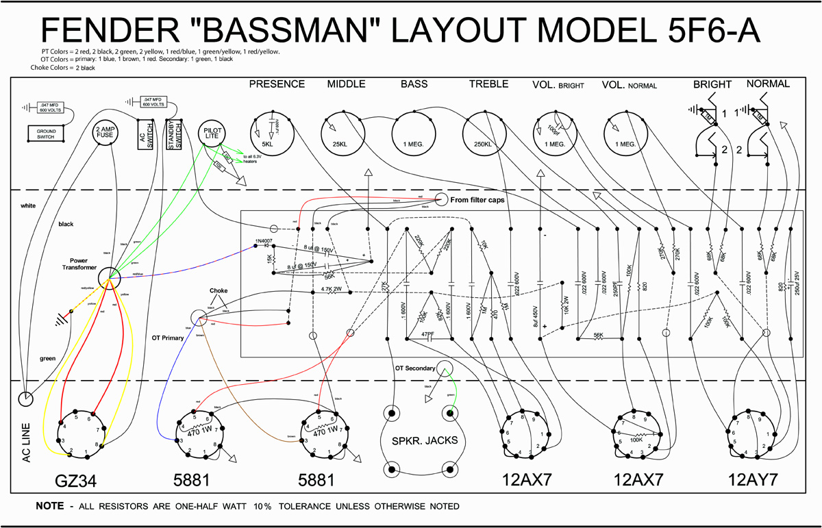
Layout
[img 771]http://www.crenshawweb.com/bassman/MK-TB-WD-low.jpg[/img]
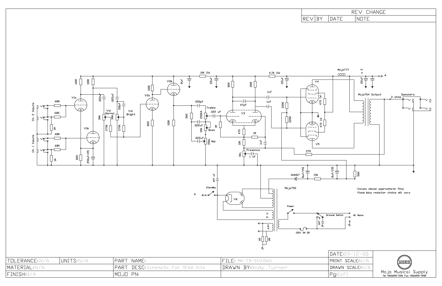
Schematic
[img 1100]http://www.crenshawweb.com/bassman/MK-TB-SCH.jpg[/img]
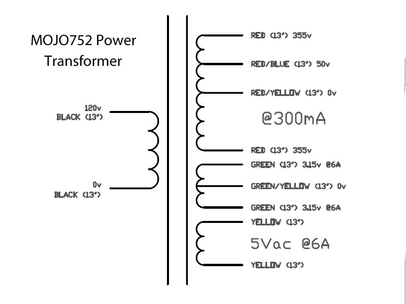
Power Trans Schematic
[img:800:600]http://www.crenshawweb.com/bassman/MOJO752.jpg[/img]
[img
 771]http://www.crenshawweb.com/bassman/MK-TB-WD-low.jpg[/img]
Schematic
[img
 1100]http://www.crenshawweb.com/bassman/MK-TB-SCH.jpg[/img]
Power Trans Schematic
[img:800:600]http://www.crenshawweb.com/bassman/MOJO752.jpg[/img]
Re: Issue With Bassman 5F6A Build
I'm considering powering up again with the recto tube in to see if I can visually locate the source of the snapping and flash. Too risky?
Peace,
Mark
Peace,
Mark

Re: Issue With Bassman 5F6A Build
I don't get Mojo sometimes; that is about the worse power transformer design than one could spec for a Tweed Bassman, that is the perfect PT to make a Tweed Bassman very loud and stiff.
Nevertheless, yes Mark install only the rectifer tube, put in the standby mode only and check the voltage at pin 8 of the GZ34.
TM
Nevertheless, yes Mark install only the rectifer tube, put in the standby mode only and check the voltage at pin 8 of the GZ34.
TM
-
martin manning

- Posts: 14308
- Joined: Sun Jul 06, 2008 12:43 am
- Location: 39°06' N 84°30' W
Re: Issue With Bassman 5F6A Build
All of the high voltage DC connections from the rectifier and the cap board are located near the presence control, so I suspect that you have some kind of arcing (the snap and flash) going on around there, possibly due to something contacting the chassis, perhaps a loose bit of wire or solder. I would look carefully for something like this before powering up again.
Re: Issue With Bassman 5F6A Build
Thanks TM.ToneMerc wrote:
Nevertheless, yes Mark install only the rectifer tube, put in the standby mode only and check the voltage at pin 8 of the GZ34.
TM
Pin 8 meters at 455VDC
Peace,
Mark
Re: Issue With Bassman 5F6A Build
Thanks. I'll give it a good look.martin manning wrote:All of the high voltage DC connections from the rectifier and the cap board are located near the presence control, so I suspect that you have some kind of arcing (the snap and flash) going on around there, possibly due to something contacting the chassis, perhaps a loose bit of wire or solder. I would look carefully for something like this before powering up again.
Peace,
Mark
Re: Issue With Bassman 5F6A Build
I found this last night but didn't think it was an issue. I touched this cap in the bias supply with the iron tip. Not sure if it's deep enough to cause arcing but it's very close to the filter cap turrets and it's positive to ground. It's 8uF 150V.
Could this be my issue?
[img:800:600]http://www.crenshawweb.com/bassman/build35.jpg[/img]
Peace,
Mark
Could this be my issue?
[img:800:600]http://www.crenshawweb.com/bassman/build35.jpg[/img]
Peace,
Mark
-
martin manning
- Posts: 14308
- Joined: Sun Jul 06, 2008 12:43 am
- Location: 39°06' N 84°30' W
Re: Issue With Bassman 5F6A Build
I looked at your pics on TDPRI... Lots of solder spatter in there. Get rid of that for sure, and vacuum out the chassis.
-
martin manning
- Posts: 14308
- Joined: Sun Jul 06, 2008 12:43 am
- Location: 39°06' N 84°30' W
Re: Issue With Bassman 5F6A Build
I think that's ok, but when I see things like that bead of solder on the chassis I think that something like that or maybe an errant strand of wire is causing the short. What's that blob between two of the eyelets below the bias cap with the melted jacket?Guitarnut wrote:I found this last night but didn't think it was an issue. I touched this cap in the bias supply with the iron tip. Not sure if it's deep enough to cause arcing but it's very close to the filter cap turrets and it's positive to ground. It's 8uF 150V.
Could this be my issue?

Re: Issue With Bassman 5F6A Build
I had my first arcing experience on a build this year and I've been tinkering with this stuff for about 10 years on and off. It was a turret board build. I did a poor job of wrapping and trimming wire at one of the filter caps. Basically, I had left a bit of bare wire end that should have been trimmed flush near the turret. It was maybe 1/8". It took me quite a while to realize the cause.
If you look closely in the area where you see the arcing, you are likely to find someplace where you left an unintended opportunity for a short. Electricity want to travel the shortest path. You may want to use a magnifying glass.
I see you posted a picture of a cap with a bit of solder on the body (or maybe where the plastic is missing). That is the kind of thing to look for. Scrape if off or goop it with something non-conductive. A dab of glue or rubber cement will work for a little spot like that.
Re: Issue With Bassman 5F6A Build
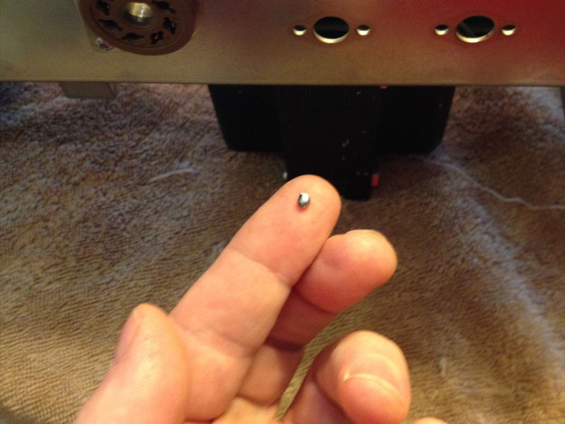
That would be this...I also removed a few smaller blobs from the same area.martin manning wrote: What's that blob between two of the eyelets below the bias cap with the melted jacket?
[img:800:600]http://www.crenshawweb.com/bassman/build41.jpg[/img]
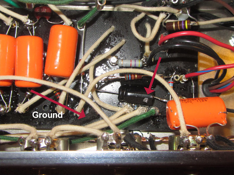
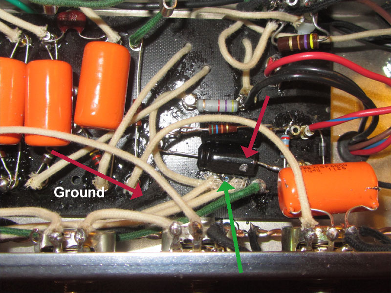
It was sitting where the green arrow is pointing.
[img:800:600]http://www.crenshawweb.com/bassman/build40.jpg[/img]
Re: Issue With Bassman 5F6A Build
Thanks Phil. If you've been at that long, you gotta figure I would have some issues on my first build.Phil_S wrote:I had my first arcing experience on a build this year and I've been tinkering with this stuff for about 10 years on and off. It was a turret board build. I did a poor job of wrapping and trimming wire at one of the filter caps. Basically, I had left a bit of bare wire end that should have been trimmed flush near the turret. It was maybe 1/8". It took me quite a while to realize the cause.
If you look closely in the area where you see the arcing, you are likely to find someplace where you left an unintended opportunity for a short. Electricity want to travel the shortest path. You may want to use a magnifying glass.
I see you posted a picture of a cap with a bit of solder on the body (or maybe where the plastic is missing). That is the kind of thing to look for. Scrape if off or goop it with something non-conductive. A dab of glue or rubber cement will work for a little spot like that.
I appreciate the input and support.
Peace,
Mark
Re: Issue With Bassman 5F6A Build
I'm going to power up again and take it out of standby. Here's hoping I'll get to check DC voltages this time.
Peace,
Mark
Peace,
Mark
Re: Issue With Bassman 5F6A Build
Thanks Martin. Makes sense. I'll be more careful in the future.martin manning wrote: I think that's ok, but when I see things like that bead of solder on the chassis I think that something like that or maybe an errant strand of wire is causing the short. What's that blob between two of the eyelets below the bias cap with the melted jacket?