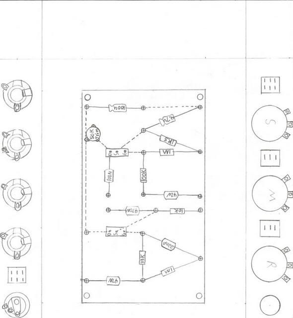
I was working on a layout for a solid state dumbleator designed by KleinM at the Brownnote Forum. I have zero experience with JFETS. I wanted to do the layout on a G10 board. Do the JFET pins have any play, can I fit them on a G10 board?
[IMG:590:640]http://i133.photobucket.com/albums/q59/ ... ulator.jpg[/img]
JFET Layout Dumbleator
Moderators: pompeiisneaks, Colossal

Re: JFET Layout Dumbleator
The legs are long enough for some wiggle room. 
Re: JFET Layout Dumbleator
They do, but i would install a Socket, they don"t like a lot of heat, use a heatsinc clamp on the leg's if you solder them in, and i have built quite a few of the Jfet circuit's, you may like the socket because i hear a difference in brand's of jfet's when used in a tone network, also the bias can be adjusted for more gain or less gain, for starters on the bais if i'm useing in a, say 9 volt application i shoot for about 1/2 the supply voltage = 4.5 VDC on the drain and then adjust from there for + or - gain, for bais voltage i normally install a 50k or 100k trimpot from B+ to drain so i can easily adjust the bais by ear for the best sound out of the circuit,
I was told along time ago by someone not to use the ECG brand Jfet, why I don't remeber, but what's funny it became 1 of my favorite Jfet's for building a Cleanboost circuit and Emulation Pedal's,
Hope this help's you in someway,
Johnhenry
I was told along time ago by someone not to use the ECG brand Jfet, why I don't remeber, but what's funny it became 1 of my favorite Jfet's for building a Cleanboost circuit and Emulation Pedal's,
Hope this help's you in someway,
Johnhenry
Last edited by Johnhenry on Tue Jun 26, 2007 7:09 am, edited 2 times in total.
-
skyboltone

- Posts: 2287
- Joined: Wed May 10, 2006 7:02 pm
- Location: Sparks, NV, where nowhere looks like home.
Re: JFET Layout Dumbleator
Add wires as needed eh?resophonic1 wrote:I was working on a layout for a solid state dumbleator designed by KleinM at the Brownnote Forum. I have zero experience with JFETS. I wanted to do the layout on a G10 board. Do the JFET pins have any play, can I fit them on a G10 board?
[IMG:590:640]http://i133.photobucket.com/albums/q59/ ... ulator.jpg[/img]
The Last of the World's Great Human Beings
Seek immediate medical attention if you suddenly go either deaf or blind.
If you put the Federal Government in charge of the Sahara Desert, in five years time there would be a shortage of sand.
Seek immediate medical attention if you suddenly go either deaf or blind.
If you put the Federal Government in charge of the Sahara Desert, in five years time there would be a shortage of sand.
-
resophonic1
- Posts: 39
- Joined: Fri Dec 08, 2006 2:19 am
Re: JFET Layout Dumbleator
Skyboltone,
It uses bluetooth technology for the connections . I did not have time to draw the wiring diagram, once I get it completed I will post the correct connections.
It uses bluetooth technology for the connections
-
resophonic1
- Posts: 39
- Joined: Fri Dec 08, 2006 2:19 am
Re: JFET Layout Dumbleator
Johnhenry,
Do you have an online source for JFET sockets?
Do you have an online source for JFET sockets?
-
skyboltone
- Posts: 2287
- Joined: Wed May 10, 2006 7:02 pm
- Location: Sparks, NV, where nowhere looks like home.
Re: JFET Layout Dumbleator
resophonic1 wrote:Skyboltone,
It uses bluetooth technology for the connections
The Last of the World's Great Human Beings
Seek immediate medical attention if you suddenly go either deaf or blind.
If you put the Federal Government in charge of the Sahara Desert, in five years time there would be a shortage of sand.
Seek immediate medical attention if you suddenly go either deaf or blind.
If you put the Federal Government in charge of the Sahara Desert, in five years time there would be a shortage of sand.
Re: JFET Layout Dumbleator
Resophonic1, check your PM,
Mouser.
Johnhenry
Mouser.
Johnhenry
Re: JFET Layout Dumbleator
Resophonic1
I just saw your question about JFET sockets. I used Mouser P/N 575-193164, 64 pin strip for sockets in my latest clone pedal. These are .100 spaced and you just cut off as many in a line as you like. Works great! Holds transistors and diodes just fine.
ampdoc
I just saw your question about JFET sockets. I used Mouser P/N 575-193164, 64 pin strip for sockets in my latest clone pedal. These are .100 spaced and you just cut off as many in a line as you like. Works great! Holds transistors and diodes just fine.
ampdoc