This is the way I would do it too. If the cap is on the eyelet board, you could use an eyelet next to the cap as a tie-point for the two shields.surfsup wrote:If I understand your question, could you just connect the two shields with a wire across the cap and ground the shield at the input side once? Both sides would then be grounded and connected as one shield with the cap in middle.
First Amp Build - Express
Moderators: pompeiisneaks, Colossal
-
JazzGuitarGimp

- Posts: 2357
- Joined: Mon Jul 23, 2012 4:54 pm
- Location: Northern CA
Re: First Amp Build - Express
Lou Rossi Designs
Printed Circuit Design & Layout,
and Schematic Capture
Printed Circuit Design & Layout,
and Schematic Capture
Re: First Amp Build - Express
I suppose I could do it that way, but is there anything wrong with what I initially suggested, ie treating the input wiring as 2 different sections coupled by a cap, and grounding each individual sections shield on one side of each section ?
Re: First Amp Build - Express
Preamp board installed and wired to the controls:
[img 768]http://img.photobucket.com/albums/v206/ ... G_1630.jpg[/img]
In the process of being wired up to the tube sockets:
[img768]http://img.photobucket.com/albums/v206/ ... G_1637.jpg[/img]
[img
 768]http://img.photobucket.com/albums/v206/ ... G_1630.jpg[/img]
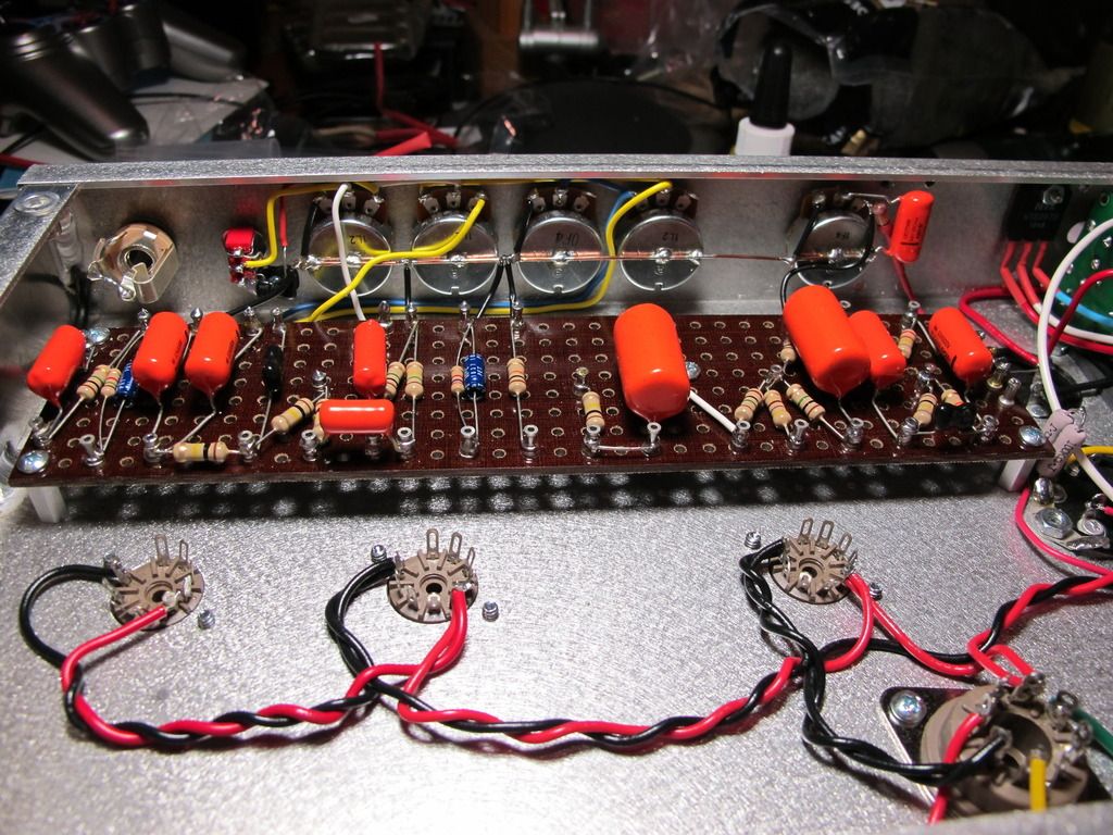
In the process of being wired up to the tube sockets:
[img
768]http://img.photobucket.com/albums/v206/ ... G_1637.jpg[/img]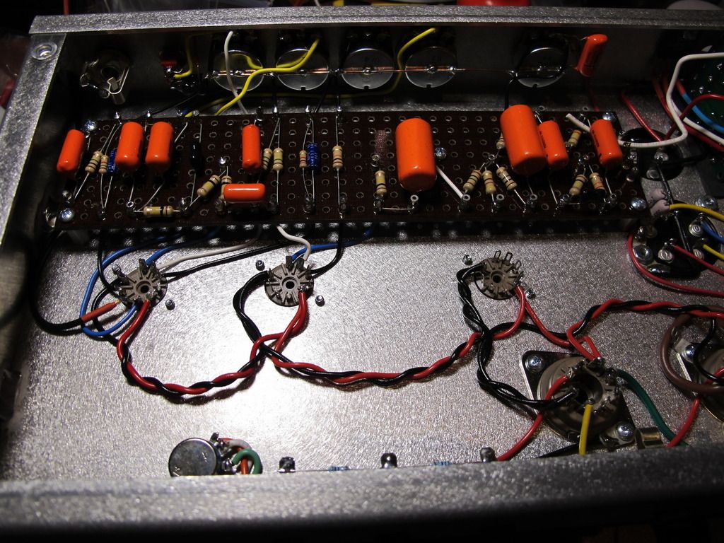
Re: First Amp Build - Express
Looks great!! my only suggestion so far would be to reduce the lenght of the white wire that goes from the volume pot to pin2 V1. Especially that wire the shorter the better.
-
martin manning

- Posts: 14308
- Joined: Sun Jul 06, 2008 12:43 am
- Location: 39°06' N 84°30' W
Re: First Amp Build - Express
Better yet use a shielded wire.redshark wrote:Looks great!! my only suggestion so far would be to reduce the lenght of the white wire that goes from the volume pot to pin2 V1. Especially that wire the shorter the better.
Re: First Amp Build - Express
I would use a shielded wire when you actually have issues but if you can get away without it is better. Rely on good lead dress practices first like positioning and lenght of wire and leave the "fixes" at last.martin manning wrote:Better yet use a shielded wire.redshark wrote:Looks great!! my only suggestion so far would be to reduce the lenght of the white wire that goes from the volume pot to pin2 V1. Especially that wire the shorter the better.
Re: First Amp Build - Express
Thanks for the comments redshark and Martin. I appreciate you guys taking the time and effort to comment, which ultimately is going to help me to ensure this project is a success. Please keep the comments and suggestions coming.
Regarding that white wire from the volume control, I don't know if you can see this in the photo, but it doesn't run direct to pin 2 on V1. It goes from the volume pot to a 0.1uf 100v DC blocking cap (look behind the 0.002 cap on the front of the board, there is an extra cap), and then from the turret under the 0.002 cap where the other lead of the blocking cap terminates, down to the V1 socket.
Those blocking caps were mentioned in the VVR kit instructions as necessary if you want to run the amp at very low power levels, which I would want to do from time to time. The other blocking cap is in line with the shielded cable from the input jack. I'm a little concerned as to what effect they will have on the tone and dynamics of the amp, and did email Dana to find out, but unfortunately he has not replied to my email, so I just installed them anyway since it was easier to do now, than at a later stage. Can anyone shed any light on this subject for me?
*Edit*, they say a picture is worth a thousand words, so I've annotated one of my previous images to point out what I have described above:
[IMG 1490]http://img.photobucket.com/albums/v206/ ... otated.jpg[/img]
Regarding that white wire from the volume control, I don't know if you can see this in the photo, but it doesn't run direct to pin 2 on V1. It goes from the volume pot to a 0.1uf 100v DC blocking cap (look behind the 0.002 cap on the front of the board, there is an extra cap), and then from the turret under the 0.002 cap where the other lead of the blocking cap terminates, down to the V1 socket.
Those blocking caps were mentioned in the VVR kit instructions as necessary if you want to run the amp at very low power levels, which I would want to do from time to time. The other blocking cap is in line with the shielded cable from the input jack. I'm a little concerned as to what effect they will have on the tone and dynamics of the amp, and did email Dana to find out, but unfortunately he has not replied to my email, so I just installed them anyway since it was easier to do now, than at a later stage. Can anyone shed any light on this subject for me?
*Edit*, they say a picture is worth a thousand words, so I've annotated one of my previous images to point out what I have described above:
[IMG
 1490]http://img.photobucket.com/albums/v206/ ... otated.jpg[/img]
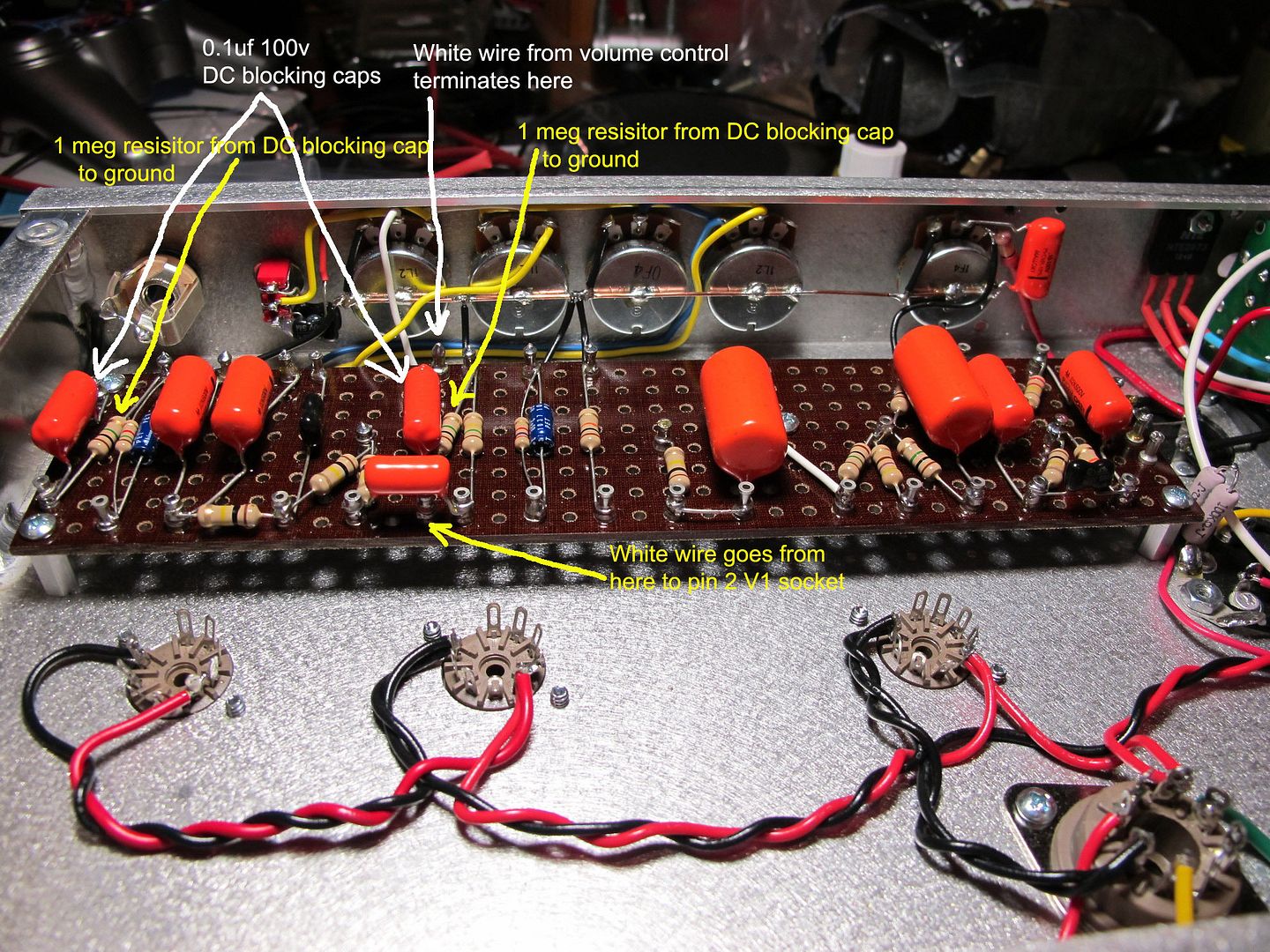
Last edited by shaunf on Thu Oct 04, 2012 1:14 pm, edited 1 time in total.
Re: First Amp Build - Express
Ok , I didn't know you were trying to scale down the amp(VVR). I have no experience with that cause I'm a purist and when I built my express I tried to be as close to an original as I could $. Anyway I would suggest you build it first using the original circuit so you know how it sounds and then do the VVR. Then you will decide what you like best. Also consider this is a temperamental amp running close to be unstable so why compromise since the beggining adding circuitry that is not there in the original design? 
Re: First Amp Build - Express
Yeah look, I'd have liked to build one that is as close to the original as possible, however since we use 220V power here, installing the cap stack is almost impossible, due to the power transformer we need, and the fact that its leads exit from both bell ends, so I had to resort to multicap cans.redshark wrote:Ok , I didn't know you were trying to scale down the amp(VVR). I have no experience with that cause I'm a purist and when I built my express I tried to be as close to an original as I could $. Anyway I would suggest you build it first using the original circuit so you know how it sounds and then do the VVR. Then you will decide what you like best. Also consider this is a temperamental amp running close to be unstable so why compromise since the beggining adding circuitry that is not there in the original design?
Also, Unfortuately without some form of attenuation or power scaling, this amp would be unusable to me most of the time. Having done a fair bit of reading on here, it seems that many people have had very good results with the VVR, as opposed to an attenuator on these amps, scaling down the whole amp, although, many do not implement the DC blocking caps, but unfortunately this limits how low power you can scale the amp to.
Also, if you look at some of the earlier pictures, the VVR is already installed.