I do want to use a tube rectifier tho, but I believe I should be able to set the bridge up using 2 diodes on the tube, right? Not sure the exact schematic but I remember reading somewhere that it can be done. So that should take care of the PT not having a CT on the HT?
2nd amp project is Finished! :D A few questions...
Moderators: pompeiisneaks, Colossal
Re: 2nd amp project is Finished! :D A few questions...
I think, I should be able to use the existing PT I have then. I just looked back at one of my threads and mentioned the voltage was 470 V on the plates but the the 50 V tap was wired together with the HT secondary to get that much. So if use only one of the taps I should have 50 AC Volts less and whatever that turns into rectified DC, right? So I could try it the 2 different voltages to see what sounds as Tubeswell suggested over at offset.
I do want to use a tube rectifier tho, but I believe I should be able to set the bridge up using 2 diodes on the tube, right? Not sure the exact schematic but I remember reading somewhere that it can be done. So that should take care of the PT not having a CT on the HT?

I do want to use a tube rectifier tho, but I believe I should be able to set the bridge up using 2 diodes on the tube, right? Not sure the exact schematic but I remember reading somewhere that it can be done. So that should take care of the PT not having a CT on the HT?

Re: 2nd amp project is Finished! :D A few questions...
You just connect your diodes to ground from the plates of your rectifier tube.
Re: 2nd amp project is Finished! :D A few questions...
What about polarity on the diodes? Cathode to ground?
Thx for all your help.
Thx for all your help.
Re: 2nd amp project is Finished! :D A few questions...
No, the cathodes (the end with the band around it) Goes to each plate of the rectifier tube.The anode end of the diode s goes to ground
-
martin manning

- Posts: 14308
- Joined: Sun Jul 06, 2008 12:43 am
- Location: 39°06' N 84°30' W
Re: 2nd amp project is Finished! :D A few questions...
See here for SS-Vacuum hybrid FWB: http://www.freewebs.com/valvewizard/bridge.html
Re: 2nd amp project is Finished! :D A few questions...
Cheers Martin and cbass, I read through the article. so for a hybrid setup... My question here is will the diodes to ground that I will be connecting to the plates on the rectifier take care of the CT for the 5V winding as well as for the CT of the HT secondary winding? (Being that the only CT on my PT is on the 6.3 V winding)martin manning wrote:See here for SS-Vacuum hybrid FWB: http://www.freewebs.com/valvewizard/bridge.html
Thx again guys. I almost have the whole picture in my head, i just have a few gaps that need to be filled.
-
martin manning
- Posts: 14308
- Joined: Sun Jul 06, 2008 12:43 am
- Location: 39°06' N 84°30' W
Re: 2nd amp project is Finished! :D A few questions...
The 5VAC winding does not use a CT- it floats at B+.
Re: 2nd amp project is Finished! :D A few questions...
Ok, so I got my power transformer however, it won't clear the cutout on the chassis unless I remove the cover. Is there any reason I should not do that or would it be okay?
Cheers
Cheers

Re: 2nd amp project is Finished! :D A few questions...
It is okay to remove the bottom cover but I would keep the top cover for shielding.
Why not enlarge the hole to fit?
Mark
Why not enlarge the hole to fit?
Mark
Re: 2nd amp project is Finished! :D A few questions...
Yeah, I think I'm going to go that way Mark. I don't have a grinder tho, ill just take the chassis to my buddy's shop. It's not much anyway. Thx 
Re: 2nd amp project is Finished! :D A few questions...
Quick update...
The PT looks nice and beefy. The only thing tho' is that one of the bolts that holds the PT just snapped in half while I was tightening the hex nut. I should get some that are a bit sturdier and replace them all maybe?
I did do a little more wiring but have to stop until probably Sunday to get the rest done.
I got to do the heater wires yet, hopefully my twisting goes ok...
Almost there!
Thx all for all the support, not just for this build but in general a big thanks to you guys
[img:800:600]http://i114.photobucket.com/albums/n271 ... 211022.jpg[/img]
[img:800:600]http://i114.photobucket.com/albums/n271 ... 211123.jpg[/img]

Re: 2nd amp project is Finished! :D A few questions...
I can understand the temptation to replace all 4. I think I'd just replace the broken one. My thinking is that it was a freak break. No need to disturb something that's not broken.
Re: 2nd amp project is Finished! :D A few questions...
Often those screws can be hard to get out due to the shellac or potting material that is sometimes used.
Tom
Don't let that smoke out!
Don't let that smoke out!
Re: 2nd amp project is Finished! :D A few questions...
Shitty. I guess, I could just leave it since I dont really gig out with my amps. :/Structo wrote:Often those screws can be hard to get out due to the shellac or potting material that is sometimes used.
Re: 2nd amp project is Finished! :D A few questions...
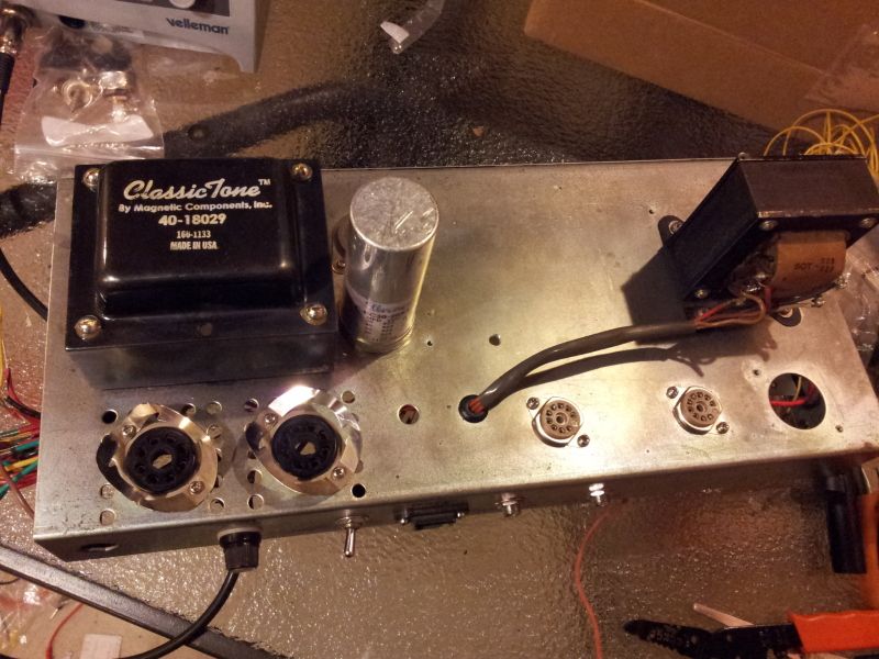
Im down to wiring the PT and the heaters wires to be done but....Can anybody help me out, im stuck here.
According to this schematic:
http://www.classictone.net/40-18029.pdf
To wire for 120 V, I need to join (BLK/BRN) and the (BLK/WHT-BRN-WHT) together right?
There's also a Red/White wire on the primary side that I don't know what it's for.
Cheers
According to this schematic:
http://www.classictone.net/40-18029.pdf
To wire for 120 V, I need to join (BLK/BRN) and the (BLK/WHT-BRN-WHT) together right?
There's also a Red/White wire on the primary side that I don't know what it's for.
Cheers
Last edited by tribi9 on Sun Sep 09, 2012 6:42 pm, edited 1 time in total.