I got my board loaded and was wondering if I can get a set of eyes to see if I made any mistakes.
There dry mounted right now. I don't have all my leads on it yet... but that will me next.
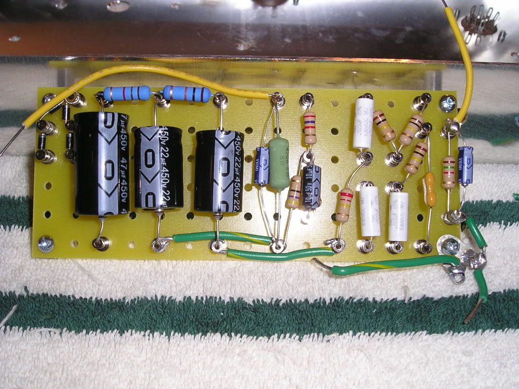
Also on the white coupling caps, I don't know if there orientated correctly. I did'nt see any way of telling which side is - & + or does it matter?
Also I still need to bridge the 2 coupling caps together and the 2 100k resistors and the 47uf cap to the diods. I got a piece of buss wire and was wondering if I should use that or just use the leads from the caps and resistors and bridge them from the under side.
Hey guys, Worked a little to late on the build last night, and while doing some soldering I brushed my Iron up against one of the White .022UF caps and melted the outer cover. Am I screwed and have to buy another cap or can I still use it? I'm thinking I will have to get another. Thoughts?
Thanks.
Chuck.
I can post pics tonight of the damaged cap if needed.
Well those caps are pretty easy to replace if the cap is bad after the board is installed. Depends on how melted it is. If it is a cosmetic sear, its probably fine but those caps I don't think are that durable and it is likely toast. But depending on where you're at in the build you might want to replace it afterward if you're itching to get going. I hate paying $10 shipping for a $1 part so I always order double what I need and now I've got plenty of spares so I can go crazy with the iron!
surfsup wrote:Well those caps are pretty easy to replace if the cap is bad after the board is installed. Depends on how melted it is. If it is a cosmetic sear, its probably fine but those caps I don't think are that durable and it is likely toast. But depending on where you're at in the build you might want to replace it afterward if you're itching to get going. I hate paying $10 shipping for a $1 part so I always order double what I need and now I've got plenty of spares so I can go crazy with the iron!
Hey Surf,
I melted the outer coating and can see a metal type screening. I live about 15 minutes from Lord Valve... so I can pick one up from him. I will probally pay more for the cap from him...but I won't have to pay shipping. Also I have been very patient on this build, seeing as it's my first build I want to have everything perfect or as perfect as I can get it.
For the tone bypass, I recieved in the kit a 3 terminal switch ( on/off/on) I know the middle terminal I solder the 22k resister and run that to ground then either of the outer terminals I run to the .022uf cap for the bass. What can I do with the other terminal? I assume I could run a different value cap there. Where would I connect that cap? Also what cap value would you guys recommend?
I have had intentions of getting my original Eagle Supre finished up and gig ready for quite a while... I think I have finally done it. The big item here was to put it into a cabinet. I built the cabinet from a DIY cabinet package that I offered with the Eagle Supre parts packages. That turned out to be a lot of work but it looks pretty good. I finished it with a "tough black" finish... similar to the truck bed-liner coating that several have mentioned here on TAG. I painted the textured cabinet black then installed a natural wood front panel. I have a lot of wood cut from local trees and this one happens to be Juniper wood. It's hard to get a piece of Juniper big enough to do anything with so I am pleased to have the front panel but probably will avoid working with this wood in the future. I also had the local graphics shop make me up a faceplate, added the old school Fender cream color knobs and loaded her up into the cabinet.
Before I loaded it into the cabinet I made a few adjustments to the circuit. I had been using a single diode for the cathode bias on the first stage and had a .1uf polycap bypass. I replaced that with the traditional 1.5K resistor and added a 22uF bypass cap. It works a lot better and sounds very Fenderish. I have the KT88 output tube in it now... very loud amp!
I made two final additions before I called it done. I tapped off the speaker output with a direct line out. Not sure if I'll use it or how it will sound but I have verified it works. Then finally I created an effects loop between the first and second gain stages. That also works and I most likely will use this feature.
I'll attach a few photos for those that are curious. I'll try to follow up with a couple posts these next few days with more info on the line out and effects loop.
rj
You do not have the required permissions to view the files attached to this post.
Last edited by RJ Guitars on Tue Dec 27, 2011 12:31 am, edited 4 times in total.
I had a friend that made a line of amps that used a similar coating rather than tolex.
That stuff was bullet proof!
Tough as nails.
I really like the natural wood you guys use on your wreck amps.
You were indeed lucky to find a large enough piece of juniper for that front.
They are mostly scrub brush around here and only some in the high desert would get large enough for any project.
blues junkie wrote:OK, I have yet another question for you guys.
For the tone bypass, I recieved in the kit a 3 terminal switch ( on/off/on) I know the middle terminal I solder the 22k resister and run that to ground then either of the outer terminals I run to the .022uf cap for the bass. What can I do with the other terminal? I assume I could run a different value cap there. Where would I connect that cap? Also what cap value would you guys recommend?
Thanks.
Chuck.
Hi Chuck, since no one else is offering I'll give it a stab.
That switch lifts the tone stack when it is open, that essentially removes the tone stack from the circuit adding gain.
So it should get louder when you open that switch.
The .022uf cap and 22K resistor form the mid frequency control for the tone stack, they just didn't put a mid pot in there.
So that switch is a three position switch?
Hmmm, I suppose you could get inventive and add another cap or resistor to the other side to have a different option.
Like a half boost.
Hey Tom,
Thanks for the post. I just jumperd the two outer terminals... so when the switch is up or down the tone stack is on and when the switch is in the center position it is in the bypass mode. The amp sounds pretty good... I'm still not happy with the amp when I run my PRS DGT through it. The amp seems a little muddy with Humbuckers. All in All, the amp came out very good for my first build.
I am going to guess that it is really the Eagle 100 with the Allied power transformer?? If so then yes that shield should go to ground. My prototype has a few unique features so don't copy it verbatim, but I did use that Allied transformer and you can see the gray lead to ground in the photo. The Eagle Supre would use an Edcor "Blue" transformer.
Let me know if my guess is wrong and confusing, otherwise the drawing should make it a little easier to sort out... just don't repeat my error in the diode and filter cap placement.
rj
You do not have the required permissions to view the files attached to this post.
768]http://i443.photobucket.com/albums/qq15 ... 010938.jpg[/img]g][/img]
 768]
768]

