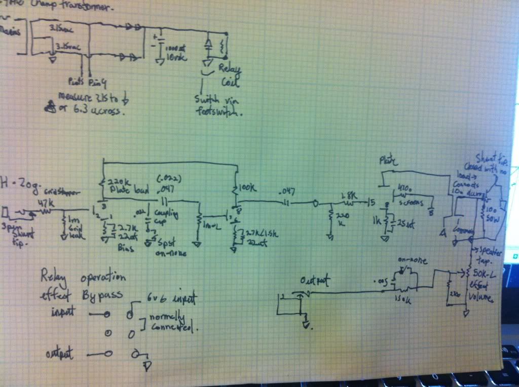
Firestorm has a good theory, but I have to mention, just because no one has, that you will measure half the heater voltage if you are measuring from the heater pins to ground, rather than across the winding (i.e.) pin 2 to 7 on the 6V6. 3.5VAC would make sense here because Hammond voltages are usually a hair high because they have a 115VAC primary instead of 120VAC. Are you actually measuring ACROSS the winding?
P.S. I converted my Tweed Princeton to the H-ZOG last night. Pretty cool! It has the switching jack so I can still use it as a practice amp. I think I'll add the footswitch too.
Low Heater Voltage on Herzog Clone
Moderators: pompeiisneaks, Colossal
-
diagrammatiks
- Posts: 558
- Joined: Sun Mar 27, 2011 12:28 am
Re: Low Heater Voltage on Herzog Clone
your heater winding is center tapped.
you should get 6.3vac across the windings.
You can use the single diode but since you have a centertapped secondary why not just full wave rectifier and get 4.41vdc for your relay.
you'll need a 3vdc or 3vdc relay though. that's not enough under load for a 5vdc relay.
...
that being said...I don't see how there's so much debate about the schematic. It's really really simple.
All it is is a champ with a direct out tapped from the output transformer and a dummy load.
hope this helps.
I'm sure people don't mind helping you...
[IMG 764]http://i625.photobucket.com/albums/tt33 ... 0fc369.jpg[/img]
but you have both the merlin books and have been given plenty of website resources...
you have access to all the info you need already.
at the same time...I would take the criticisms from others with a grain of salt. If they had the answer for you...it would have been easy enough to help you. This forum can get snarky sometimes...there are always those that think they know better.
you should get 6.3vac across the windings.
You can use the single diode but since you have a centertapped secondary why not just full wave rectifier and get 4.41vdc for your relay.
you'll need a 3vdc or 3vdc relay though. that's not enough under load for a 5vdc relay.
...
that being said...I don't see how there's so much debate about the schematic. It's really really simple.
All it is is a champ with a direct out tapped from the output transformer and a dummy load.
hope this helps.
I'm sure people don't mind helping you...
[IMG
 764]http://i625.photobucket.com/albums/tt33 ... 0fc369.jpg[/img]
but you have both the merlin books and have been given plenty of website resources...
you have access to all the info you need already.
at the same time...I would take the criticisms from others with a grain of salt. If they had the answer for you...it would have been easy enough to help you. This forum can get snarky sometimes...there are always those that think they know better.
-
marcoloco961
- Posts: 356
- Joined: Wed Feb 25, 2009 3:07 pm
- Location: Colona, Il. U.S.
Re: Low Heater Voltage on Herzog Clone
Did ya make any progress Steve? I'm curious.

Re: Low Heater Voltage on Herzog Clone
Steve, I'm truly sorry if I offended and or insulted you as I didn't mean too. I admire that you have tons of enthusiasm and that fact that you have stuck with this when others would have quit.The New Steve H wrote:I enjoy posting here and getting valuable input on building and understanding amplifiers. I am polite to everyone here. I acknowledge response and thank people for their time. I haven't done anything to justify hostile or insulting comments. You will never see me posting an obnoxious comment about anyone else. I am an easygoing person. I don't bully people or harp on their mistakes. I don't flip out over trivia. I think my way is the right way to go through life.No, you chose to take that path. You are a self sadist, you love pissing into the wind uphill. Before you order parts or pick up a soldering iron you need to do more due diligence in order to prevent yourself from kicking your own butt.
I tried to understand this circuit before I built it. I scoured the web for schematics, and I came up with the half-baked drawings I have posted here. I asked question after question. I searched for and downloaded documents related to similar 5-watt single-ended amps. Really, there is a limit to what I can do, short of hiring an electrical engineer. Even experienced builders do not understand this schematic; their opinions on it conflict drastically. This is my fourth amp, and I have no training apart from a basic electronic course I took in college. I'm doing my best. I am not proactively trying to fail.
I could have chosen something easy, like a kit. But that's just soldering practice. I'm always going to look for projects that are more interesting.
If you have helpful advice, I'm glad to hear it. If you're just irritated because I chose a confusing project, why not ignore my posts instead of posting personal remarks? I'm sorry I made you angry, but I don't think there is anything I can do to prevent it from happening in the future. Truthfully, I think the mods should delete this whole exchange, in order to preserve the atmosphere of the board. I want to discuss amps, not personalities.
I'm going to take a break from posting. I don't want to cause a breakdown of civility. I'll figure this amp out on my own. If anyone wants to send advice via PM, I will be very grateful.
Thanks for the help, Firestorm. I'll poke around in the amp and try to apply what you told me.
I really just hate to see that you work yourself to death with these builds and I don't want to see you to burn yourself out. My suggestion is maybe just slow down, grasp more of the concepts and then pick up the soldering iron.
Please don't run off because of what I or anyone else said, this is your forum too and you are family, therefore there's no need to stop posting for awhile.
What can I do to help you along?
Mike
-
The New Steve H

- Posts: 1047
- Joined: Mon May 30, 2011 11:24 pm
Re: Low Heater Voltage on Herzog Clone
Thank you for posting that. As I said in a PM, maybe I misunderstood.
It is true that I need to get up to speed on the concepts. I find that it's easier to learn while I have a project in front of me, though, and sometimes I get so engrossed in a real amp, I end up working so much on it that I am too tired to study later. That's something I'll have to get control over; it's very tough to put down the soldering iron when I should.
I've been locating some new study material I know will be helpful.
Relax. It's SUPPOSED to smoke a little.
-
The New Steve H
- Posts: 1047
- Joined: Mon May 30, 2011 11:24 pm
Re: Low Heater Voltage on Herzog Clone
Heaters are running. I rewired the relay stuff and corrected some errors. The amp makes noise, but so far, just a faint hum. Will be going through it again. I want to make sure I have all the switches wired correctly, and that I'm not turning things off when I think I'm turning them on.
It's a little weird to see a circuit where one side of the heater transformer is grounded, instead of having a center tap to ground.
It's a little weird to see a circuit where one side of the heater transformer is grounded, instead of having a center tap to ground.
Relax. It's SUPPOSED to smoke a little.
-
diagrammatiks
- Posts: 558
- Joined: Sun Mar 27, 2011 12:28 am
Re: Low Heater Voltage on Herzog Clone
it's not really grounded. it's ac through one winding.
back and forth. back and forth.
ac is weird.
back and forth. back and forth.
ac is weird.
-
The New Steve H
- Posts: 1047
- Joined: Mon May 30, 2011 11:24 pm
Re: Low Heater Voltage on Herzog Clone
Here is the news.
The heaters work. The relay works. The output stage makes noise. It looks like the problem is between the plate on V1 and the volume wiper. If I poke around near V2, I can get scrapy sounds.
If you look at the schematic (the one with the footswitch included), you will see a .047uF cap and a 470uF cap attached to the V1 plate. It goes plate--->.047--->volume pot--->470. The polarity on the 470uF cap is correct, so that can't be it. I checked all the electrolytics.
The junction of the .047 and 470 caps goes to the V2 grid via a pot wiper, so if I get nothing there, the amp is dead.
Measuring at the V1 plate, I get 205V DC. Using my trusty Ebay oscilloscope, I can clearly see that guitar signals are getting to the plate. On the other side of the .047uF cap, however, I get 0.473 VDC and zero signal. I tried to measure the signal here as DC and AC, but nothing shows up. I don't know if this is a bias issue or what. I do not understand how the signal could just vanish inside the capacitor, if the bias is okay.
Voltages, in case they mean anything (measured with volume high):
Volume wiper: 0.42
V1 cathode: 1.80
V2 cathode: 1.98
V2 plate: 191
Above 220k resistors to plates: 355
Ground: 0
Regarding the heater AC, I believe it's currently wired up wrong, because I forgot to remove the center tap to ground. Nonetheless, the heaters and relay work, so I am not fooling with it until I get this other stuff figured out.
Got a Schaum outline and a Problem Solvers book on the way, so I will not remain so far behind all the geniuses here.
Relax. It's SUPPOSED to smoke a little.

Re: Low Heater Voltage on Herzog Clone
.5V is too much DC leakage. I'd replace that coupling cap and go from there. It could be putting dc on the following stages grid messing that stage up. Maybe why your not getting sound. Either way I'd replace the cap.
-
The New Steve H
- Posts: 1047
- Joined: Mon May 30, 2011 11:24 pm
Re: Low Heater Voltage on Herzog Clone
Is there a way to test your theory, other than replacing the cap?
I have extras (Orange Drop 600V), but I figured I should ask before taking the cap out.
I don't understand why the guitar signal is not reaching the far side of the coupling cap. Wouldn't it still be there, even if DC got through? The problem isn't just that I can't hear it. It's not present on an oscilloscope. It doesn't exist.
Relax. It's SUPPOSED to smoke a little.
Re: Low Heater Voltage on Herzog Clone
Yes that .047uf cap should block all DC voltage from the grid of the 6V6.
Any DC there will screw up the bias on the 6v6.
Any DC there will screw up the bias on the 6v6.
Tom
Don't let that smoke out!
Don't let that smoke out!
-
The New Steve H
- Posts: 1047
- Joined: Mon May 30, 2011 11:24 pm
Re: Low Heater Voltage on Herzog Clone
Thanks for the answer, but does it explain why the AC part of the signal doesn't show up on the scope? Wouldn't it still show up after the coupling cap if there were a DC leak?
I guess I should replace it while I'm waiting around, since it's obviously a problem.
I guess I should replace it while I'm waiting around, since it's obviously a problem.
Relax. It's SUPPOSED to smoke a little.
-
The New Steve H
- Posts: 1047
- Joined: Mon May 30, 2011 11:24 pm
Re: Low Heater Voltage on Herzog Clone
Replaced the cap. DC voltage down to 0.5-0.8. Still no signal.
Relax. It's SUPPOSED to smoke a little.
Re: Low Heater Voltage on Herzog Clone
Because that is what capacitors are supposed to do: pass AC, store DC. That cap is not supposed to be 470uF; it's 470pF (a thousand times smaller). It's there to cut some of the brightness, by passing very high frequencies to ground. With a 470uF cap there, you are passing ALL frequencies to ground, so no signal. And that cap is also storing the minute amount of DC that you are reading. Change the cap to 500pF, or 1000pF, or try leaving it out, or wire in the Bright switch from the other schematic.The New Steve H wrote:I do not understand how the signal could just vanish inside the capacitor, if the bias is okay.
That damn schematic strikes again.
-
The New Steve H
- Posts: 1047
- Joined: Mon May 30, 2011 11:24 pm
Re: Low Heater Voltage on Herzog Clone
Oh God. You have to be kidding me.
Maybe the schematic was intended as a practical joke.
I guess I should have realized 470uF was kind of high. It seemed strange to me when I ordered it, but I figured Garnet Gillies knew more than I did.
Thanks for pointing this out. I should be able to fix this right now.
I hope someone will give me credit for blazing a trail for other people who might want to build one of these things. I may have aggravated people, but when this is over with, I will be able to generate a schematic that works.
Relax. It's SUPPOSED to smoke a little.