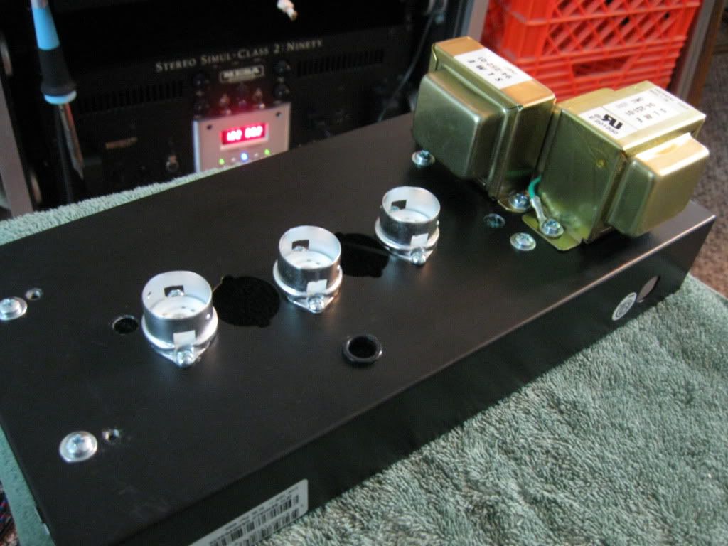
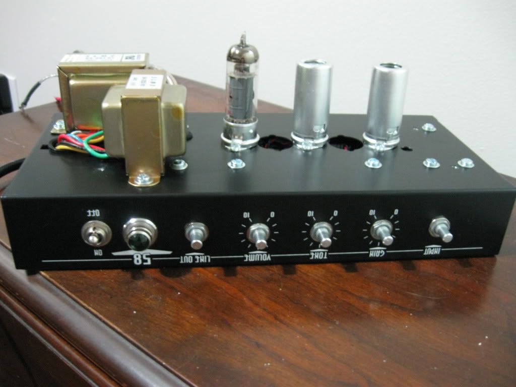
It began as a Crate V58. I added a 12AX7 and a 3 knob tone stack. I started out with 3 gain stages and a bootstraped cathode follower, but it oscillated bigtime. Then I went to a regular cathode follower, but didn't like the compression. Then I tried 4 gain stages, which was to much! Then on to a parallel triode driven tone stack which was cool with it's unique distortion character. But I decided that it was to round for what I like. The power section was cathode biased thus far.
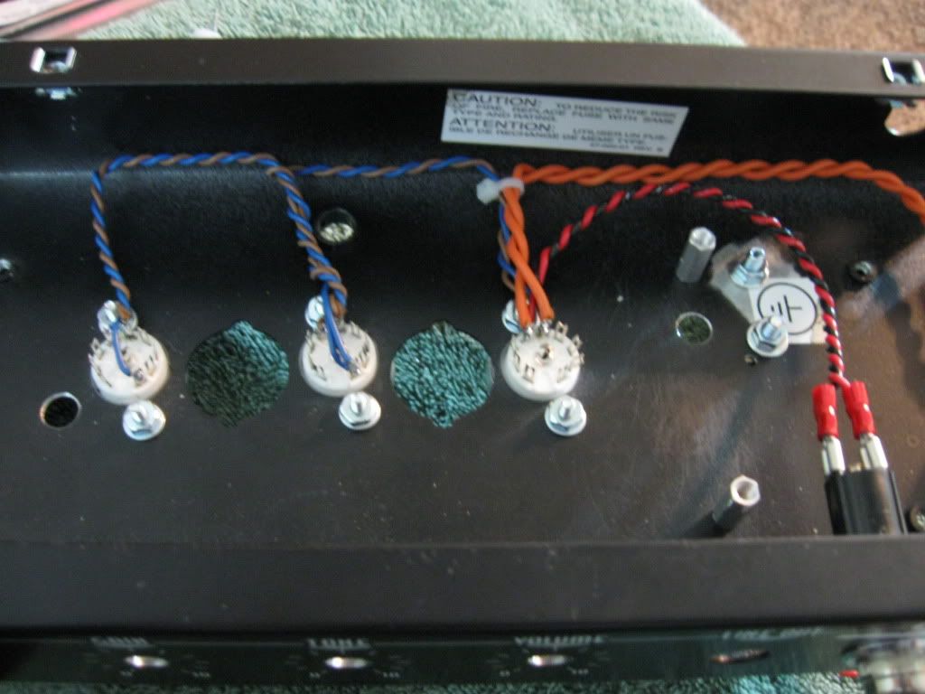
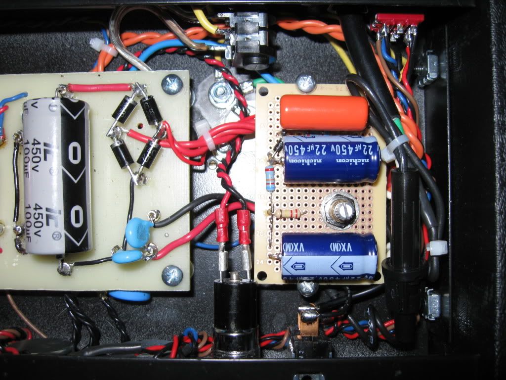
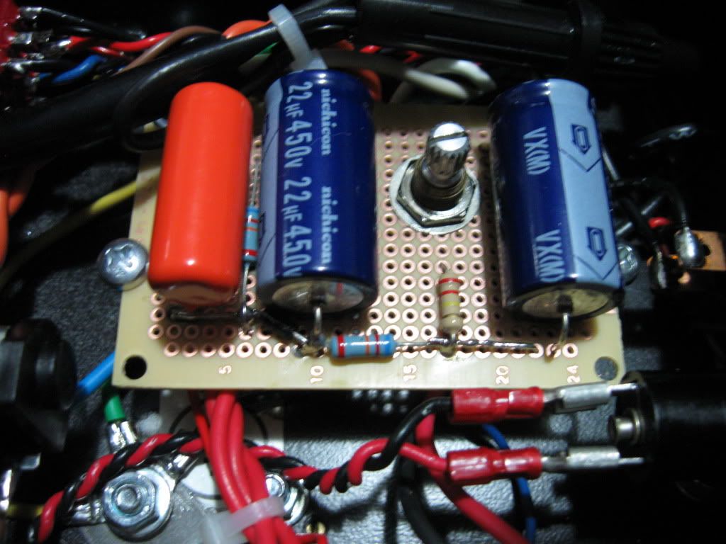
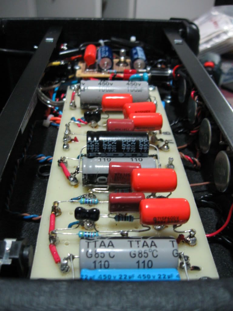
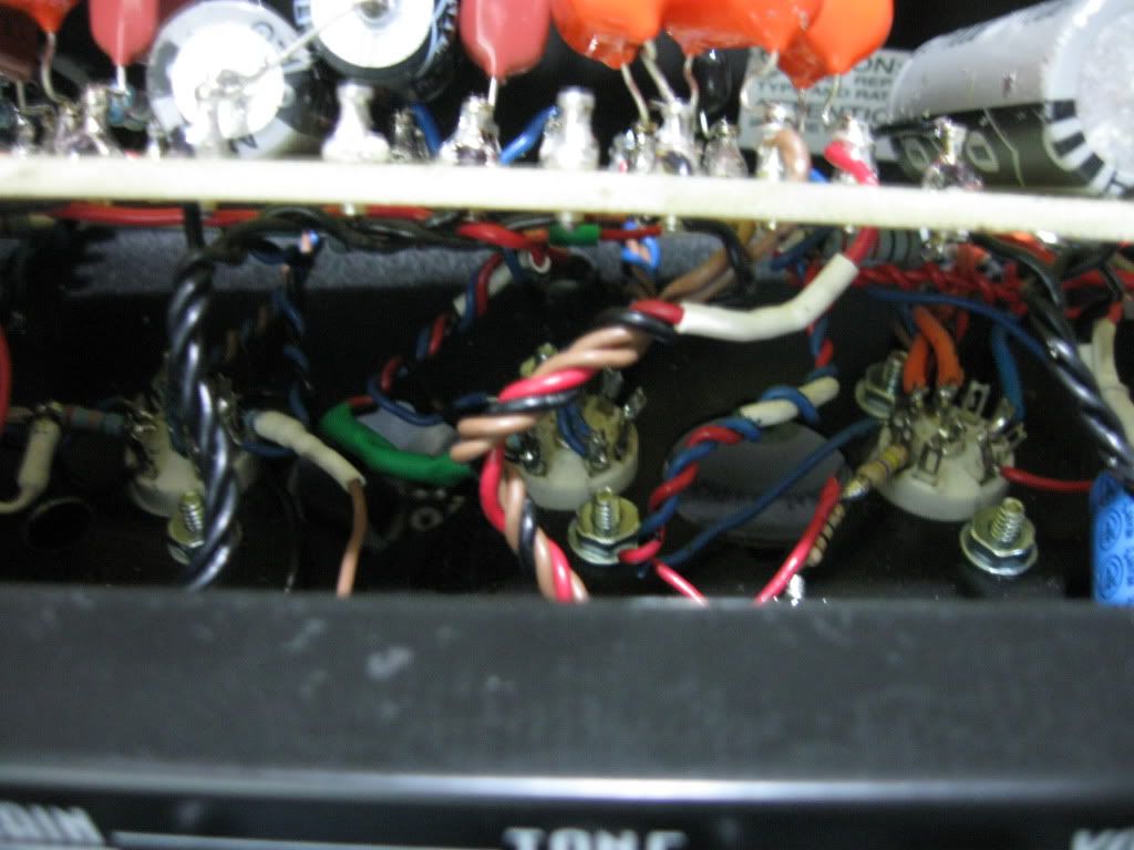
Now I'm on 3 stages of gain with a plate driven tones stack, and fixed bias! It seems to be the most articulate so far. I managed to pack it all in there. I changed a lot of stuff along the way. You can see some empty lugs, and jumpered ones too, not to mention the piggy back filtering.
I used the stock cliff jacks for an input on the back, along with a speaker out when I don't wanna use the stock 8" speaker.
I learned a lot, and am still learning, and am not to proud to change a thing, except for the tone stack position. I'd prolly like it better after the 1st gain stage. But not on this amp. It was a lot of work to get it where it is. Beside it's my first amp...
I was inspired to add a master volume bypass after reading about Trainwrecks. There IS a slight difference in dynamics, and clairity with no MV.
Kudos. I am amazed how neat you have kept this through all those changes in such a tight space. Did you draw up scaled layouts before or just jump in at the deep end?
overtone wrote:Kudos. I am amazed how neat you have kept this through all those changes in such a tight space. Did you draw up scaled layouts before or just jump in at the deep end?
Thanks, and yeah. It took me a couple of days to draw up a decent layout. I made a copy of it, and used it as a template to drill my board. I also used it for reference when I started to build. It helped a lot with the wiring as I already worked out what went where.
Is the schematic wrong or is that how the input is actually wired? The 1M resistor should go to the tip of the input jack so that it is always connected to the input.
Looks good for a first build and packing it all in that space.
Jana wrote:Is the schematic wrong or is that how the input is actually wired? The 1M resistor should go to the tip of the input jack so that it is always connected to the input.
Looks good for a first build and packing it all in that space.
I've been posting versions of this amp on other sites for a little while, and you're the 1st person to point out that mistake! Good eyes.
leadfootdriver wrote:... except for the tone stack position. I'd prolly like it better after the 1st gain stage. But not on this amp.
The way you have it in the schematic is not ideal from preserving bandwidth etc. A TMB tonestack is a hi-load after a conventional inverting triode stage, and without a further 'recovery' stage after the stack, you won't get as-good a current for driving the output tube grid. (Compare it with BF fender stacks which have a recovery stage after the stack, or with Fender 5F6A and Marshall derivatives, which has a CF stage to help drive the stack with a good current).
One simple suggestion is to try a higher current tube (e.g.: a 12AT7 or 12AU7) in the stage that is driving the tonestack and see what difference that makes. You obviously won't have a much gain as a 12AX7 stage, but that might not be a bad thing. JM2CW
Oh man, I forgot to mention the 12AT7. I had that in the original designs. I was crankin' about 6-7 ma's thru the tone stack when I was doing a cathode follower! I was maxing out the specs on the PT as the voltages on the whole amp would drop. The amp would get warm to say the least!
After trying the AT7 in different configs, I felt that the amp had less bandwidth then wiht an AX7. MAybe it wouldn't be so hard to put the tonestack earlier in the chain. Really you're only swithcing around a few wires, and swap resistors and caps. As long as I don't get any oscillations.
I had an AX7 on this version. The parallel triode IS really nice. It has a cool distortion character, but it's better suited for a more laidback attack.
Well, that was way easier than I thought it would be. I only had to switch 4 wires, jumper a coupling cap, and add one at the master volume to place the tonestack after the 1st stage. I did it all with alligator clips.
But I think that a single ended EL84 is way to loose and rich for a Trainwreck layout, I tried bypassing the 1st 2 stages with 22uf's, but it was way bloated. I did notice that the attack had a leathery quality to it tho, which might be cool on the real thing.
No big deal, and at least I don't have to wonder anymore.

 2496]http://home.comcast.net/~leadfootdriver/Version%204.JPG[/img]
 768]http://i258.photobucket.com/albums/hh26 ... G_0354.jpg[/img]
 2448]http://home.comcast.net/~leadfootdriver/bias.JPG[/img]
