
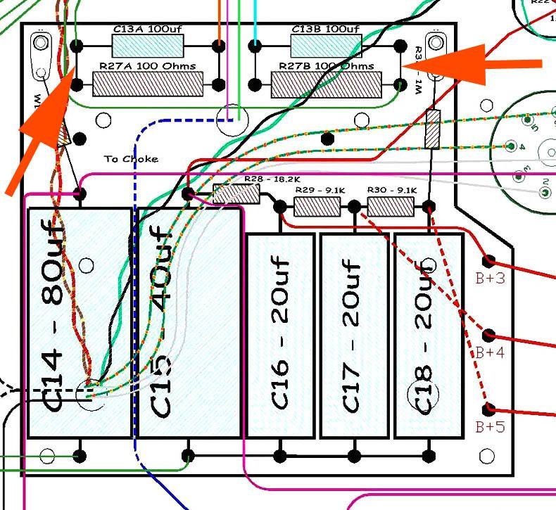
On this type of cap setup for the 1/2 power switch, my amp does not have the jumpers that are shown with the red arrows. It works fine. can it be set up both ways.
[IMG:790:725]http://i260.photobucket.com/albums/ii9/ ... erRR-1.jpg[/img]
Rocket power caps
Moderators: pompeiisneaks, Colossal

Re: Rocket power caps
Can't tell exactly in the schem snippet, but it looks like that side gets grounded. So, if both resistors and both caps are grounded, you are fine.
-
martin manning

- Posts: 14308
- Joined: Sun Jul 06, 2008 12:43 am
- Location: 39°06' N 84°30' W
Re: Rocket power caps
Ange, I'm assuming that in this layout the brown and blue leads from the inner C13 cap/R27 resistor junctions are connected to the cathodes of pairs of the power tubes, one to the inner pair and one to the outer pair. And, the two green leads at the outer junctions are to be grounded, except if you want half-power, in which case one of them is un-grounded by a switch to take a pair of tubes out of the circuit.
If the jumpers you point to are omitted, then the cathode resistors R27A and R27B, are not bypassed by the C13's, and this would reduce power considerably. Is it possible that in some arrangements the half power switch un-grounds the cathode bypass caps to reduce power? Can you point to or post an example of a layout without the jumpers?
If the jumpers you point to are omitted, then the cathode resistors R27A and R27B, are not bypassed by the C13's, and this would reduce power considerably. Is it possible that in some arrangements the half power switch un-grounds the cathode bypass caps to reduce power? Can you point to or post an example of a layout without the jumpers?
Re: Rocket power caps
Have you used an ohm meter to verify that the two points in question are not interconnected? They could be jumpered under the board.
Removing the bypass caps only has a minor impact on power out. It does effect whether or not degenerative feedback is applied to the cathode, and does effect distortion.
There is a good article on Aiken Amps by Mitchell on the subject:
http://www.aikenamps.com/cathcap.pdf
Removing the bypass caps only has a minor impact on power out. It does effect whether or not degenerative feedback is applied to the cathode, and does effect distortion.
There is a good article on Aiken Amps by Mitchell on the subject:
http://www.aikenamps.com/cathcap.pdf
Under board
Yes, I did pull the board up to actually look at it, and it is not jumpered.
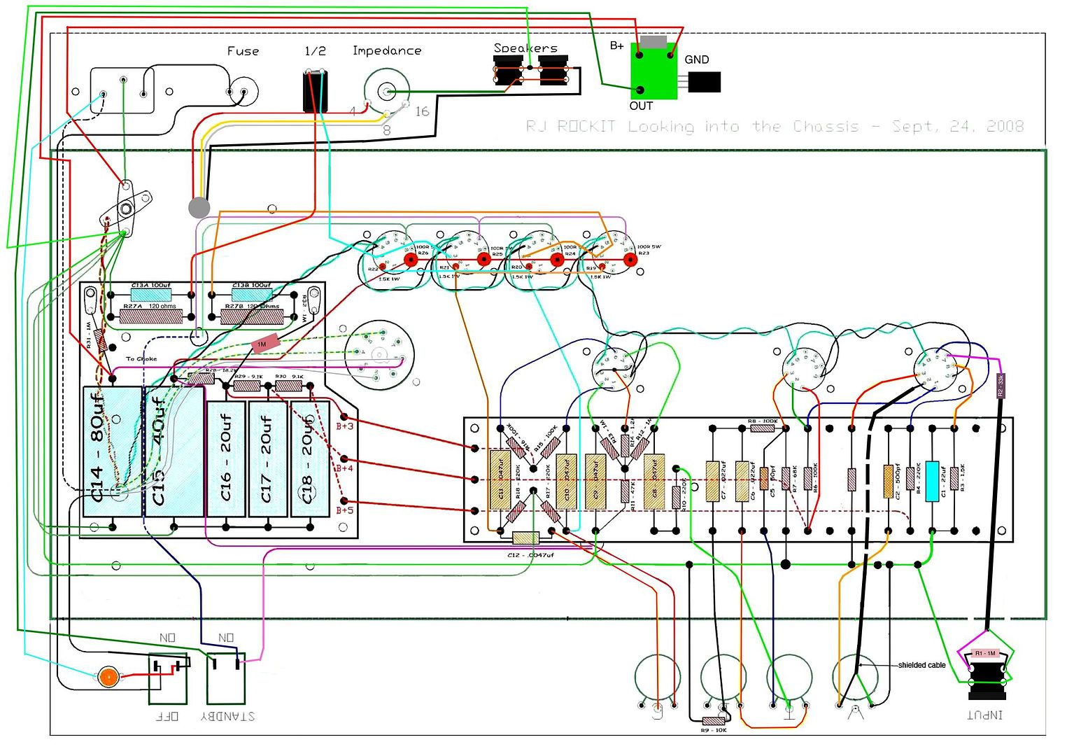
Here is the layout for my amp... Some how I missed those two wires and been running the amp all this time.
[IMG 1504]http://i260.photobucket.com/albums/ii9/ ... copy-1.jpg[/img]
Here is the layout for my amp... Some how I missed those two wires and been running the amp all this time.
[IMG
 1504]http://i260.photobucket.com/albums/ii9/ ... copy-1.jpg[/img]
Last edited by angelodp on Sun Dec 05, 2010 6:14 pm, edited 1 time in total.
Re: Rocket power caps
If they had been in a triode gain stage it would have effected gain a lot more.
Since it is a bypass in the cathode of the pentode output stage where the output is current though a transformer (instead of voltage to a load impedance) it has little effect on gain.
Since it is a bypass in the cathode of the pentode output stage where the output is current though a transformer (instead of voltage to a load impedance) it has little effect on gain.
jumpered
Ok, thanks to all and Colossal for the eyes on this. I just soldered it in after listening to it jumpered. Nice change, there was a low residual hum on this amp that I could not get out, that's gone. Now have great clarity, more headroom and the chime is killer. Onto the reverb install.
thanks Ange
thanks Ange

Re: Rocket power caps
One cathode bias resistor will need to be 50 ohms for 36watt mode and the other side needs to be 68 ohms or higher when engaged in the 18watt mode.
The bias is 50R until the switch is flipped and then it goes to 120R running on 18watts.
Mark
The bias is 50R until the switch is flipped and then it goes to 120R running on 18watts.
Mark
Re: Rocket power caps
Yes,
Correct me if I'm wrong please!
But the layout you converted was for octal powered Rocket with cathode bias at 200 ohms; therefore, the two 100 ohm resistors are on the board.
The common resistance for an 18 watt amp is 120-130 ohms. (Two EL84)
The common resistance for a 36 watt amp is 50 ohms. (Four EL84)
I used 50R (ohms) and 68R (ohms) which is less than 120R but readily available 10 watt resistor values.
Mark
correction
Sorry for the confusion, I amended my layout to show the real value of those two bias resistors which are 120R each. I also had left out a 1M resistor to the B+3 node.
Re: Rocket power caps
So this is switching the resistors in parallel? 120R + 120R
Then you have 60R at 36w mode and 120R at 18w mode.
Mark
Then you have 60R at 36w mode and 120R at 18w mode.
Mark
-
RJ Guitars

- Posts: 2663
- Joined: Tue Nov 14, 2006 3:49 am
- Location: Los Alamos, New Mexico
- Contact:
Re: Rocket power caps
Angelo,
that is a great success story, thanks for sharing so the masses can add that little tidbit to our collective wisdom. A little hum that shouldn't be and maybe you don't miss the chime if you never had it but once you do then you could never go back! Chime is the Rocket's (AC-30) middle name. Glad you got yours to deliver!
I choose the 120 Bias resistors on my amp like this one because I really like the sound. You might or might not hear a difference if you replaced the the 120 Ohm resistors with 100 Ohm resistors. I have thought about it but when I play through mine I really don't have any inspiration to change things. I think the sound is a little more complex with all four tubes working together and a bit more edgey in the half power setting.
If you ever get the chance an audio clip would be a good way to share a bit more about this amp.
rj
Good, Fast, or Cheap -- Pick two...
http://www.rjguitars.net
http://www.rjaudioresearch.com/
http://diyguitaramps.prophpbb.com/
http://www.rjguitars.net
http://www.rjaudioresearch.com/
http://diyguitaramps.prophpbb.com/
Great amp
RJ, I am working things out to ready for the reverb install. Thanks for your continued support. Here is a look at where I am at currently in terms of planning. This represents a photoshopped version of the virtual amp. I have been playing with this method of working out the topography before the build. Lots of help from Rawnster, Colossal, MFowler, MartinM, Structo, ChrisM, JackieT.... and of course Normster who has gifted this great addition of reverb to this circuit. Many thanks gentlemen.
I am still working out a boost switch and may try what Structo implemented with a jack and foot pedal. I have the VVR and 1/2 power in there, but the PPIMV is on the table for experimentation and I will try it out before drilling more holes.
To be clear, I built an RJ Rocket with the RJ group build and now I will be post installing the reverb circuit.
I will post a new thread on this as the build takes place.
[IMG 1043]http://i260.photobucket.com/albums/ii9/ ... tual-3.jpg[/img]
I am still working out a boost switch and may try what Structo implemented with a jack and foot pedal. I have the VVR and 1/2 power in there, but the PPIMV is on the table for experimentation and I will try it out before drilling more holes.
To be clear, I built an RJ Rocket with the RJ group build and now I will be post installing the reverb circuit.
I will post a new thread on this as the build takes place.
[IMG
 1043]http://i260.photobucket.com/albums/ii9/ ... tual-3.jpg[/img]
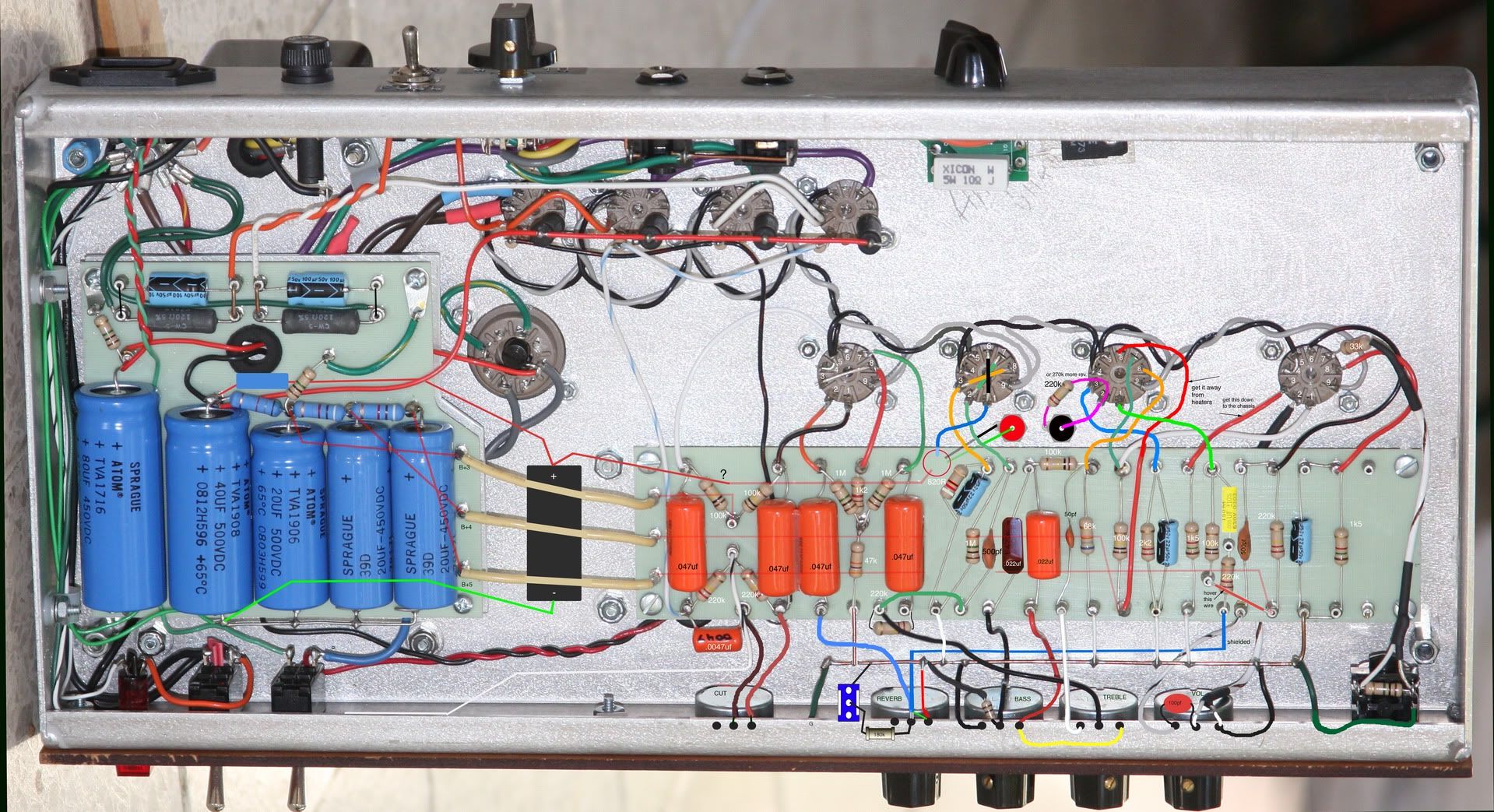