Help me troubleshoot my in progress Princeton build.
Moderators: pompeiisneaks, Colossal
Re: Help me troubleshoot my in progress Princeton build.
Secondaries measure 630 VAC. I dont use the ground wire on my cord to measure. Will there be a significant difference in the reading by not wiring a ground when measuring the voltage?
Re: Help me troubleshoot my in progress Princeton build.
So that appears to be a 315-0-315 PT.
Tom
Don't let that smoke out!
Don't let that smoke out!
Re: Help me troubleshoot my in progress Princeton build.
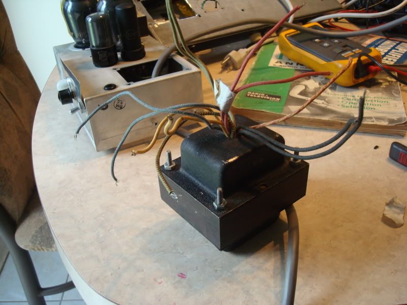
So I scored this used fluke MM and took some proper measurements....
One voltage on the tall PT is a bit odd....
The voltage from the wall is 124 VAC
This is what I got...
I have this wide one. I have a champ chassis that I cut to fit it. This one measures:
From one leg of the HT to center tap 341V , same as the other leg so 341-0-341
The green wires 6.9 V
The yellow 5.9 V
The Blue 7.3 V
[IMG:800:600]http://i114.photobucket.com/albums/n271 ... C02599.jpg[/img]
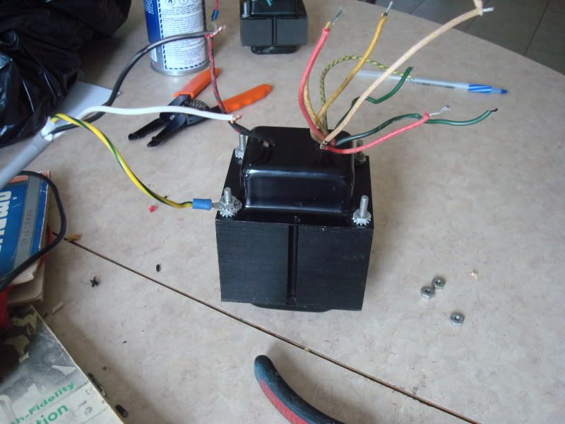
The second tall one measures
Secondary 387-0-387
Yellow 6.5 V
Green 17.2 V???
[IMG:800:600]http://i114.photobucket.com/albums/n271 ... C02600.jpg[/img]
One voltage on the tall PT is a bit odd....
The voltage from the wall is 124 VAC
This is what I got...
I have this wide one. I have a champ chassis that I cut to fit it. This one measures:
From one leg of the HT to center tap 341V , same as the other leg so 341-0-341
The green wires 6.9 V
The yellow 5.9 V
The Blue 7.3 V
[IMG:800:600]http://i114.photobucket.com/albums/n271 ... C02599.jpg[/img]
The second tall one measures
Secondary 387-0-387
Yellow 6.5 V
Green 17.2 V???
[IMG:800:600]http://i114.photobucket.com/albums/n271 ... C02600.jpg[/img]
Re: Help me troubleshoot my in progress Princeton build.
Just for safety purposes, you can accomplish the same thing w/ a 6VAC or 12VAC source and some math. Those bare live mains and HT leads just scare the crap out of me.tribi9 wrote:So I scored this used fluke MM and took some proper measurements....
One voltage on the tall PT is a bit odd....
The voltage from the wall is 124 VAC
This is what I got...
I have this wide one. I have a champ chassis that I cut to fit it. This one measures:
From one leg of the HT to center tap 341V , same as the other leg so 341-0-341
The green wires 6.9 V
The yellow 5.9 V
The Blue 7.3 V
[IMG:800:600]http://i114.photobucket.com/albums/n271 ... C02599.jpg[/img]
The second tall one measures
Secondary 387-0-387
Yellow 6.5 V
Green 17.2 V???
[IMG:800:600]http://i114.photobucket.com/albums/n271 ... C02600.jpg[/img]
Matt
Re: Help me troubleshoot my in progress Princeton build.
The HT voltage (341v) will drop quite a bit once a load is put on it.tribi9 wrote:So I scored this used fluke MM and took some proper measurements....
One voltage on the tall PT is a bit odd....
The voltage from the wall is 124 VAC
This is what I got...
I have this wide one. I have a champ chassis that I cut to fit it. This one measures:
From one leg of the HT to center tap 341V , same as the other leg so 341-0-341
The green wires 6.9 V
The yellow 5.9 V
The Blue 7.3 V
I think most likely the red wire with the yellow stripe will be the HT center tap.
The green with yellow stripe is probably the heater center tap (6.9v)
The 5.9v is the 5v rectifier tap and is usually not center tapped.
As far as the blue wires go, are there two of them?
I'm not sure what those would be for.
It really depends on the current rating of the transformer is, if it isn't very high, then those voltages will come way down.
You should see if you can't cross reference the numbers on the trannys to see if you can find some data on them.
There weren't that many companies making them so you should be able to find something out about them.
If you use solid diodes to rectify it, you take 1.4 x 341= 477 but that would probably drop down to around 450v under load.
For a 5U4 the voltage would be 1.21 x 341 = 412 - 40v = 372 or so.
But more likely 350v with a load.
These are rough guesstimates.
Last edited by Structo on Tue Jun 15, 2010 7:55 pm, edited 1 time in total.
Tom
Don't let that smoke out!
Don't let that smoke out!
Re: Help me troubleshoot my in progress Princeton build.
Those will drop a wee bit under loadtribi9 wrote:The voltage from the wall is 124 VAC
This is what I got...
I have this wide one. I have a champ chassis that I cut to fit it. This one measures:
From one leg of the HT to center tap 341V , same as the other leg so 341-0-341
The green wires 6.9 V
The yellow 5.9 V
The Blue 7.3 V
The green is good for a relay supply or an SS power railtribi9 wrote:The second tall one measures
Secondary 387-0-387
Yellow 6.5 V
Green 17.2 V???
Re: Help me troubleshoot my in progress Princeton build.
Weird. I'm going to double check the green just to make sure as the PT powered a 5Z4 and a 6SL7 and that voltage on the green just doesn't seem right.tubeswell wrote:The green is good for a relay supply or an SS power railtribi9 wrote:The second tall one measures
Secondary 387-0-387
Yellow 6.5 V
Green 17.2 V???
BTW Tubeswell congrats on the tie today! I watched the game.
Re: Help me troubleshoot my in progress Princeton build.
Yes That's what the wires are. I measured continuance between the Secondaries and their respective CT's when applicable and then I measured the voltage referenced to the CT.Structo wrote: The HT voltage (341v) will drop quite a bit once a load is put on it.
I think most likely the red wire with the yellow stripe will be the HT center tap.
The green with yellow stripe is probably the heater center tap (6.9v)
The 5.9v is the 5v rectifier tap and is usually not center tapped.
As far as the blue wires go, are there two of them?
I'm not sure what those would be for.
It really depends on the current rating of the transformer is, if it isn't very high, then those voltages will come way down.
You should see if you can't cross reference the numbers on the trannys to see if you can find some data on them.
There weren't that many companies making them so you should be able to find something out about them.
If you use solid diodes to rectify it, you take 1.4 x 341= 477 but that would probably drop down to around 450v under load.
For a 5U4 the voltage would be 1.21 x 341 = 412 - 40v = 372 or so.
But more likely 350v with a load.
These are rough guesstimates.
Yes there are 2 blue wires I guess just an extra tap. I can just probably just cut it short. Electrical tape it off.
I'll look up the numbers see if I can find anything.
I want to build a Princeton non reverb AA964 with a diode rectifier. I need about 420V on the B+ and I want to use this short fat PT.
Re: Help me troubleshoot my in progress Princeton build.
I was pretty amazed myself.tribi9 wrote:BTW Tubeswell congrats on the tie today! I watched the game.
Re: Help me troubleshoot my in progress Princeton build.
Sorry to back on something here...tubeswell wrote: The -ve bias voltage is supplied to the 6V6 grids via the 2 x 220k grid load resistors, via the trem intensity pot.
So does this mean when I use the intensity pot my tubes can go from being biased cold to hot and viceversa?
What is the reason for not having a dedicated bias pot on the AA964?
Re: Help me troubleshoot my in progress Princeton build.
Yeah... that's what bias-vary trem does. (That's why you need to run the bias slightly cooler on bias vary trem amps BTW. When eth trem kicks in, the 'average' bias heats up - esp on slower oscillationstribi9 wrote:So does this mean when I use the intensity pot my tubes can go from being biased cold to hot and viceversa?tubeswell wrote: The -ve bias voltage is supplied to the 6V6 grids via the 2 x 220k grid load resistors, via the trem intensity pot.
No you still need to set the overall bias, and for that reason it better to have a bias adjustment feature. All those early Fender amps just didn't bother with it because a fixed resistor was 'close enough'tribi9 wrote:What is the reason for not having a dedicated bias pot on the AA964?
Re: Help me troubleshoot my in progress Princeton build.
Recap.... (Sort of)
So I decided a while ago that I was going to build a BFPR Non Reverb. I have the chassis from my former vibrochamp and the layout on the champ's faceplate matches the AA964 Blackface Princeton Non Reverb.
This time Im trying to understand what the circuit is actually doing as opposed to just piecing it together like a puzzle, like I did when i built my Vibrochamp. Even tho I have some sort of curse where my mind starts wondering half way through reading anything and everything I lay my eyes upon, I believe I'm making some sort of progress.
So piecing all the random questions I usually ask here at the forum, I came up with this variation on the AA964 design I guess.
Being that I'm going to fit it in a Vibrochamp chassis, I will need to go with the diode rectifier. I only have two 9 pin sockets and two octal, plus I dont really have room for an extra socket.
I want it to run 6L6G's so I know now that all I need to do is to beef up the cathode resistor to 10W and/or maybe increase the size a bit. The problem is on the AA964 I don't know what the cathode resistor is on the the layout/schematic Pin 8 on the 6V6 is referred straight to ground on the schematic. I know what it is on the vibrochamp because it runs from the cathode Pin 8 but not on the AA964.
http://www.ampwares.com/schematics/princeton_aa964.pdf
I looked the spec sheet for 6L6G's and it says that in Pentode mode the load resistance should be 3.8K.
So here I get a little confused... The data sheet says that the max. voltage on the plate should not exceed 360 V. Since I'm expecting around 450 VDC on the plates, will the higher voltage affect my OT requirements or am I good just getting an OT with a 4K primary?
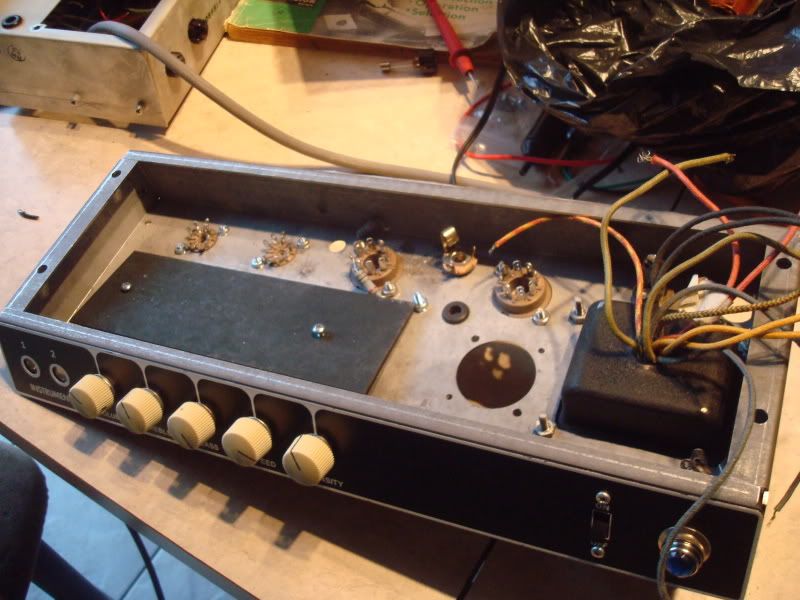
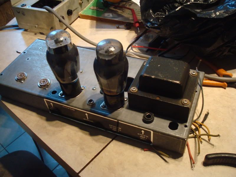
BTW on an unimportant side note Im making my own turret board.

Here some pics of my cleaned up Vibrochamp chassis, future PR. Work in progress...
[IMG:800:600]http://i114.photobucket.com/albums/n271 ... C02617.jpg[/img]
[IMG:800:600]http://i114.photobucket.com/albums/n271 ... C02615.jpg[/img]
So I decided a while ago that I was going to build a BFPR Non Reverb. I have the chassis from my former vibrochamp and the layout on the champ's faceplate matches the AA964 Blackface Princeton Non Reverb.
This time Im trying to understand what the circuit is actually doing as opposed to just piecing it together like a puzzle, like I did when i built my Vibrochamp. Even tho I have some sort of curse where my mind starts wondering half way through reading anything and everything I lay my eyes upon, I believe I'm making some sort of progress.
So piecing all the random questions I usually ask here at the forum, I came up with this variation on the AA964 design I guess.
Being that I'm going to fit it in a Vibrochamp chassis, I will need to go with the diode rectifier. I only have two 9 pin sockets and two octal, plus I dont really have room for an extra socket.
I want it to run 6L6G's so I know now that all I need to do is to beef up the cathode resistor to 10W and/or maybe increase the size a bit. The problem is on the AA964 I don't know what the cathode resistor is on the the layout/schematic Pin 8 on the 6V6 is referred straight to ground on the schematic. I know what it is on the vibrochamp because it runs from the cathode Pin 8 but not on the AA964.
http://www.ampwares.com/schematics/princeton_aa964.pdf
I looked the spec sheet for 6L6G's and it says that in Pentode mode the load resistance should be 3.8K.
So here I get a little confused... The data sheet says that the max. voltage on the plate should not exceed 360 V. Since I'm expecting around 450 VDC on the plates, will the higher voltage affect my OT requirements or am I good just getting an OT with a 4K primary?
BTW on an unimportant side note Im making my own turret board.
Here some pics of my cleaned up Vibrochamp chassis, future PR. Work in progress...
[IMG:800:600]http://i114.photobucket.com/albums/n271 ... C02617.jpg[/img]
[IMG:800:600]http://i114.photobucket.com/albums/n271 ... C02615.jpg[/img]
Re: Help me troubleshoot my in progress Princeton build.
IMHO you want to get the 6L6s idling between about 16W to 21W if you are using 5881s, or you can go higher if you have 6L6GCs. Size the cathode resistor accordingly to get the ballpark dissipation. Ballpark equation is:tribi9 wrote: I came up with this variation on the AA964 design I guess.
I want it to run 6L6G's so I know now that all I need to do is to beef up the cathode resistor to 10W and/or maybe increase the size a bit. The problem is on the AA964 I don't know what the cathode resistor is on the the layout/schematic Pin 8 on the 6V6 is referred straight to ground on the schematic. I know what it is on the vibrochamp because it runs from the cathode Pin 8 but not on the AA964.
tube dissipation (W) = (plate voltage - cathode voltage) x (cathode voltage/cathode resistance)
As you noted, use a 10W resistor and you can't go wrong. I'd start with around 250R to 330R (270R) for 2 x 6L6
Being cathode bias, you'll want to increase the slam in the trem circuit (if you are going to keep that). 6L6s need a bigger voltage to drive the grids, so they need a bigger wiggle to get bias-vary trem working.
6L6s will run good between 2k5 to 6k6 with optimal load resistance between about 3k2 to 4k, so 4k is goodtribi9 wrote:I looked the spec sheet for 6L6G's and it says that in Pentode mode the load resistance should be 3.8K.
So here I get a little confused... The data sheet says that the max. voltage on the plate should not exceed 360 V. Since I'm expecting around 450 VDC on the plates, will the higher voltage affect my OT requirements or am I good just getting an OT with a 4K primary?

Re: Help me troubleshoot my in progress Princeton build.
What happened with the VC? You worked so hard to get it going, now your using it's chassis?
Re: Help me troubleshoot my in progress Princeton build.
Yeah, I wasn't happy with it.ChrisM wrote:What happened with the VC? You worked so hard to get it going, now your using it's chassis?
Where is the cathode resistor in the schematic tho'? I can't locate it. The cathode on the schem doesn't show a resistor coming out of it.
http://www.ampwares.com/schematics/princeton_aa964.pdf