The problem with that is that the bias voltage needs to be negative.tribi9 wrote:Thank you tubeswell. See what confuses me a bit is that Pin 2 and 8 are both filaments on a 5U4GB. Pin 8+ supplies 420VDC to the OT. So wouldn't Pin 2 which is tied to Pin 8 be able to supply 420V minus whatever resistor+cap combo needed to get the appropiate rectified voltage needed to the grid eliminating the need for that diode?
How could I wire the bias cap if I decide to build this amp using diode rectification and this PT with no center tap. The only way I know how to do it is with a CT on the PT.
If you follow the link that martin manning posted, there's a schematic there in a post by talbany that shows exactly how to do it.
Since a 6L6G is a 23W tube w/ a max plate voltage of 360, voltage-wise, you should be ok w/ this tranny. When you say that each of the secondary measured at 375VAC, is that in reference to each other, ground, or some other winding?
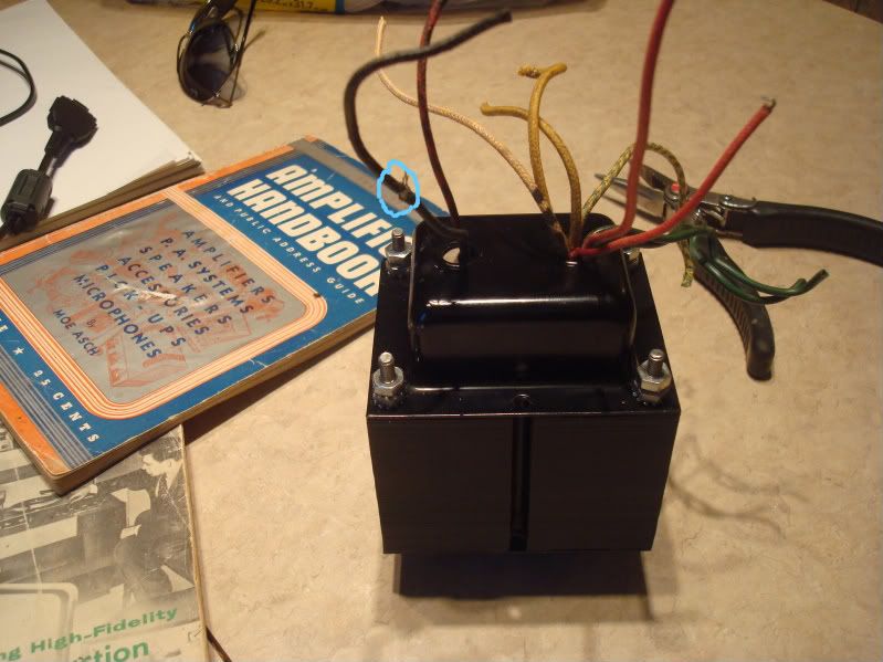
Morcey the PT used to power 2 6L6G's. It was from a movie projector amp.
It has 5 and a 6.3 V taps each of the secondary measured 375V. That's all I know.
What strikes me as odd is that if this has a 5V rectifier heater winding and supplied power to a set of 6L6G's, the odds are that there is a tap that you're missing somewhere. The only situation that I can think of where you would have a non-CT winding on a PT from that era is if it used a half-wave rectifier instead of a full wave bridge since a full wave bridge w/ tube rectifiers, while possible and do-able, are complicated and unwieldy.
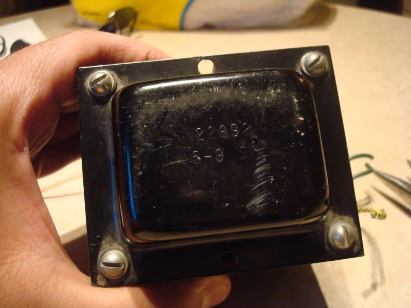
Do you know what the rectifier originally used was? Any way you can post some pictures of the tranny?
Matt
