
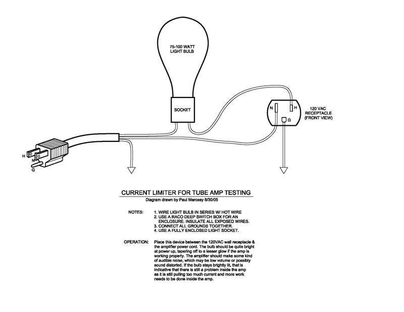
Does anyone know where I can obtain plans and use info for the current limiter that uses a lightbulb that some use at start up????
Also, when checking continuity on my heater wires when I touch the black lead at the beginning of the path at the first socket and black lead at the end of the path at the indicator light I get signal. When I touch black at beginning and red at the end, I also get signal??? If I reverse, and do red begin to red end I get signal and red begin to black end, I get signal again?? shouldn't I only get signal red to red and black to black??? Hope I made sense..... The start up makes me a little nervous this is my second build and much more complex than the 5e7 Bandmaster I did first.
Thanks
Current limiter and heater wire continuity question..
Moderators: pompeiisneaks, Colossal
Current limiter and heater wire continuity question..
You do not have the required permissions to view the files attached to this post.

Re: Current limiter and heater wire continuity question..
The bulb limiter is in the Trainwreck files section under the Express build guide has instructions and the BOM file has the parts list.
As far as the continuity tester you are going to get continuity everywhere you touh even the transformer you cannot go by that type of testing in the amp. Check it, out black to ground and check the heater wiring, jacks and trannies it lights up right?
Just follow your layout and check it against the schematic. Go over your wiring, lead dress and make sure your solder joints are good.
Mark

Re: Current limiter and heater wire continuity question..
There is also a very good description of the dim bulb tester and how to use it here: http://www.antiqueradio.org/dimbulb.htm
As for filament string continuity, I wouldn't be all that concerned. Probably the most common problem is a bad solder. This happens because you've got a double wire in the pin and lack of experience with it sometimes leaves it with a cold solder. This is easily fixed. When you plug in your tubes, if you have one that doesn't light up, you'll know it.
The other way to check it is to power up the amp with no tubes in it. Put your meter on ACV and from the top side of the tube socket (where the tube goes, not the pins where you solder) and probe the 12AX7 socket at the end of the chain, one probe to pin 9 and the other on pin 4, then pin 9 to pin 5. You should get the same result, about 6.3vac. Work back towards the first socket in the chain. Remember the power tubes if EL34/6V6'6L6 have filament connections on pins 2 and 7. Don't jam your probes into the sockets. You don't want to open them up and then they won't hold the tube pins.
Re: Current limiter and heater wire continuity question..
Here's how I made mine.
[IMG:800:618]http://i23.photobucket.com/albums/b392/ ... iter-1.jpg[/img]
When you first fire up the amp without tubes use a 25 watt bulb.
This limits the current to the amp quite a bit and helps form the filter caps better.
Then put a 40 watt, 60 watt and 75 watt.
This gradually builds up the voltage too.
The bulb will flash when you first power up, that's just the caps charging.
The bulb should go down to a low glow.
If it stays brightly lit, then you have a short somewhere and you should power down immediately.
Tom
Don't let that smoke out!
Don't let that smoke out!
Re: Current limiter and heater wire continuity question..
Thanks guys.................
-
dano-rator

- Posts: 150
- Joined: Mon Oct 06, 2008 5:25 pm
- Location: s.jersey
Re: Current limiter and heater wire continuity question..
Also, this limiter from geofex:
http://www.geofex.com/Article_Folders/SPO_Test.htm
I think it's been posted here before. The nice things about it are the indicator switch, and that it's all contained in a metal junction box. Whatever you use, just be sure the bulb is wired in SERIES with the HOT side of the plug.
http://www.geofex.com/Article_Folders/SPO_Test.htm
I think it's been posted here before. The nice things about it are the indicator switch, and that it's all contained in a metal junction box. Whatever you use, just be sure the bulb is wired in SERIES with the HOT side of the plug.
Re: Current limiter and heater wire continuity question..
It really is a great and simple device.
When you first power up with a 25 watt bulb you are limiting the current to the amp to around 1/4 amp.
So not only will this alert you to any defective wiring in the power supply but will also be a soft power up that will be easy on the filter caps.
Even if it is an old amp that hasn't been turned on in a long time it can help reform the filter caps and help to form new filter caps if you gradually increase the wattage of the light bulbs up through the available wattage bulbs.
So I use a 25, 40, 60, and finally a 75 watt bulb.
Tom
Don't let that smoke out!
Don't let that smoke out!

Re: Current limiter and heater wire continuity question..
Hijack...
I always use a Variac which is plugged into an Isobar that has a 15A breaker on it.
But it does not indicate if there is a short.
First power up, or very old questionable amp-I pull the tubes and clip two meters on, one to B+, another to the filament leads.
If I don't see 25% voltage on the meters at 30-40VAC
on the Variac, then I don't push it any further and check to see what's going on.
I guess if there is a dead short then it would pop the fuse on the Variac.
Should I build the light bulb limiter and not use the Variac to do this?
Or is the Variac method good enough?
Re: Current limiter and heater wire continuity question..
Well I don't own a variac so I use this poor mans device.
Although some day I'll get one.
I had a friends amp that he had built on my bench one day.
He wasn't very knowledgeable and this was his first build.
I had already fixed a couple wiring mistakes but was a little leery of just powering it up without protection.
Sure enough, when I turned it on the bulb stayed real bright so I immediately powered down.
There was an under board wire on the power supply that wasn't right.
Once I corrected that mistake I was able to power it up and take some voltage readings.
Only then did I install the tubes.
So it earned it's place on my meager bench.
And the ability to limit the current to the amp is a big plus.
Tom
Don't let that smoke out!
Don't let that smoke out!

Re: Current limiter and heater wire continuity question..
Sorry to bump this...
I have made a limiter (finally after building five amps lol). Now I put in a 60W lightbulb.
I turn on the main's switch and the bulb grows bright. It stays like this. I think this is ok as there are no tubes in and all that is in the circuit is the first filter cap. Should I flip on the standby switch and see what happens?
-
martin manning

- Posts: 14308
- Joined: Sun Jul 06, 2008 12:43 am
- Location: 39°06' N 84°30' W
Re: Current limiter and heater wire continuity question..
Seems like there is something wrong. The bulb should glow briefly, then once the first filter is charged it should dim. Something is continuing to draw significant current, so I'd check everything on the PT side of the standby. What voltages do you have for B+, Bias, heater, and relay supply?ChrisM wrote:Sorry to bump this...
I have made a limiter (finally after building five amps lol). Now I put in a 60W lightbulb.
I turn on the main's switch and the bulb grows bright. It stays like this. I think this is ok as there are no tubes in and all that is in the circuit is the first filter cap. Should I flip on the standby switch and see what happens?
MPM
Re: Current limiter and heater wire continuity question..
On the D'Lite most of the filtering is after the standby switch.
Tom
Don't let that smoke out!
Don't let that smoke out!
Re: Current limiter and heater wire continuity question..
Yes, if the standby breaks the connection to all filter caps, I guess that bulb is going to glow like it's in a regluar light bulb circuit. When you close the standby and allow the filter caps to charge, it should glow very brightly for a very, very brief moment, and then go dim. The first time you charge caps, it may take a few extra moments.