2nd amp project is Finished! :D A few questions...
Moderators: pompeiisneaks, Colossal
-
martin manning

- Posts: 14308
- Joined: Sun Jul 06, 2008 12:43 am
- Location: 39°06' N 84°30' W
Re: 2nd amp project is Finished! :D A few questions...
You have the 120V primary connections right. On the Red-White, are you saying there are three Red-White wires and not just two? Is the orange shield wire present?
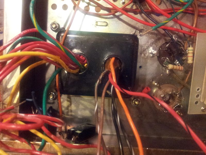
Re: 2nd amp project is Finished! :D A few questions...
Sorry Martin, I meant to write extra Red/Black on the primary side, not Red/White. This guy here in the pic.martin manning wrote:You have the 120V primary connections right. On the Red-White, are you saying there are three Red-White wires and not just two? Is the orange shield wire present?
[IMG:800:600]http://i114.photobucket.com/albums/n271 ... 145229.jpg[/img]
-
martin manning
- Posts: 14308
- Joined: Sun Jul 06, 2008 12:43 am
- Location: 39°06' N 84°30' W
Re: 2nd amp project is Finished! :D A few questions...
You could test for continuity with the other windings and try to figure out what it might be, but I'd send an e-mail to Magnetic Components and ask them directly. The were very helpful when I asked about product specs recently. If the Black-Red has continuity with one of the other primary windings, it might be a 220V tap to be used when the two primaries are in series.
Re: 2nd amp project is Finished! :D A few questions...
It does have continuity to all the other primaries. Should I then just put a piece of electrical tape on its end?
-
martin manning
- Posts: 14308
- Joined: Sun Jul 06, 2008 12:43 am
- Location: 39°06' N 84°30' W
Re: 2nd amp project is Finished! :D A few questions...
It has continuity to the other windings with them connected as for 120V (expected) or all unconnected? Probably yes you'll end up insulating it and just using the connections as shown on the drawing. The best way to do that is to cut off the bare part of the wire, fold the end over ~1/2" and put a piece of heat-shrink on it.
Last edited by martin manning on Sun Sep 09, 2012 7:53 pm, edited 1 time in total.
Re: 2nd amp project is Finished! :D A few questions...
Both, there is continuity connected as a 120 V and when tested one by one on each one of the other primaries. Thx for the heat shrink tip. 
-
martin manning
- Posts: 14308
- Joined: Sun Jul 06, 2008 12:43 am
- Location: 39°06' N 84°30' W
Re: 2nd amp project is Finished! :D A few questions...
This is odd, because it says that the two primaries are connected together somehow even if the leads are not connected together. Do you get continuity between the two primaries with all leads unconnected?tribi9 wrote:Both, there is continuity connected as a 120 V and when tested one by one on each one of the other primaries. Thx for the heat shrink tip.
Re: 2nd amp project is Finished! :D A few questions...
Also, on a transformer schematic what represents 'live', the top part of the diagram? Or is my schematic slightly half assed and just missing a bit of info? 
-
martin manning
- Posts: 14308
- Joined: Sun Jul 06, 2008 12:43 am
- Location: 39°06' N 84°30' W
Re: 2nd amp project is Finished! :D A few questions...
Polarity on the primary doesn't matter for the mains connection. It does for the series/parallel 120/240 connections, but that is taken care of with the color coding of the leads. Clearly the drawing is missing information about the Red-Black wire, though.tribi9 wrote:Also, on a transformer schematic what represents 'live', the top part of the diagram? Or is my schematic slightly half assed and just missing a bit of info?
Re: 2nd amp project is Finished! :D A few questions...
There is continuity if I hook it up as a 120 V, there's also continuity to the black and to the red/Black. There's no continuity to the brown and to the brown/White. Sorry, the reason I thought I got continuity last time was because one side of the primary was still wired as 120 V and I just half assed the reading. My apologies.martin manning wrote:This is odd, because it says that the two primaries are connected together somehow even if the leads are not connected together. Do you get continuity between the two primaries with all leads unconnected?tribi9 wrote:Both, there is continuity connected as a 120 V and when tested one by one on each one of the other primaries. Thx for the heat shrink tip.
-
martin manning
- Posts: 14308
- Joined: Sun Jul 06, 2008 12:43 am
- Location: 39°06' N 84°30' W
Re: 2nd amp project is Finished! :D A few questions...
If you mean Red-Black has continuity to the Black/Black-White primary but not to the other one, then that makes sense and I think it's likely to be a tap for another foreign voltage.
If you want to find out connect an AC voltage to the Brown/Brown-White primary, and measure the voltage from Black to Black-White and to Black-Red, and from Black-White to Black-Red. From those you should be able to figure it out. Or you can just insulate it and forget it.
If you want to find out connect an AC voltage to the Brown/Brown-White primary, and measure the voltage from Black to Black-White and to Black-Red, and from Black-White to Black-Red. From those you should be able to figure it out. Or you can just insulate it and forget it.
Re: 2nd amp project is Finished! :D A few questions...
Yes, black/White. Sorry Martin, thats what I wanted to write. Thx for your help.martin manning wrote:If you mean Red-Black has continuity to the Black/Black-White primary but not to the other one, then that makes sense and I think it's likely to be a tap for another foreign voltage.
If you want to find out connect an AC voltage to the Brown/Brown-White primary, and measure the voltage from Black to Black-White and to Black-Red, and from Black-White to Black-Red. From those you should be able to figure it out. Or you can just insulate it and forget it.
Re: 2nd amp project is Finished! :D A few questions...
So I had a lot more left to go than I thought, I still have to ground all the components on the one side of the board. All the underwiring is done so Ijust have to run a single wire to a ground. Half the pots are done, the secondary needs to be wired and ill be done. 
I spent a fair bit of time reworking some areas. I MM tested everything for continuity and everything checks out but I need to stop now. I'm tired.
Ill double check everything again tomorrow.
Progress pic and once again a big thx to all of you.
[IMG:800:600]http://i114.photobucket.com/albums/n271 ... 232323.jpg[/img]
Re: 2nd amp project is Finished! :D A few questions...
Im finally done. Well, one last thing before i flip the switch on. The tab that connects to the speaker output has a path to ground is this right? I would have thought there shouldn't have been one.
Re: 2nd amp project is Finished! :D A few questions...
Damn, i just turned it on and there is no sound. Arghhhh...