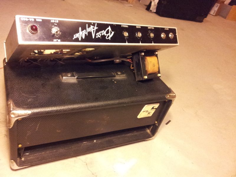
Remember this amp?
[img:800:600]http://i114.photobucket.com/albums/n271 ... 144606.jpg[/img]
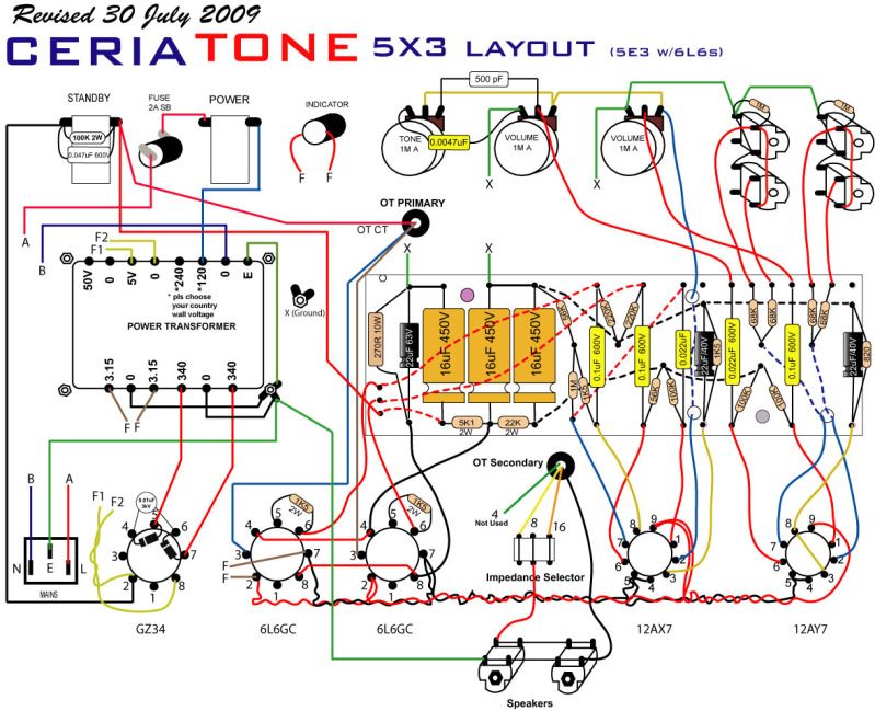
Well, unfortunately while trying to troubleshoot a hissing issue a while back, I ended up burning out a trace on the PCB. I'll be the first to admit that I should be sent to amp hell; however, Im going to try to make it up. I placed an order at Ceriatone for a blank 5X3 board. Here is the schematic:
[IMG:799:649]http://i114.photobucket.com/albums/n271 ... iatone.jpg[/img]
I already have most of the components here.
I do need a Power Transformer. My PT chassis cutout is 2-3/4 x 3-7/16 and I need a 340-0-340 V PT so I still need to find a PT. The Output Transformer ill be using is the 6k into 4 ohms OT that came stock with this amp.
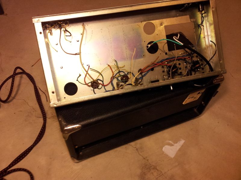
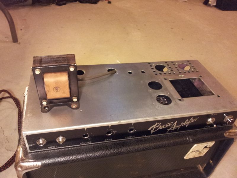
I cleaned the chassis, unfortunately that kinda messed it up. At first I used diluted "Groove Juice" it started looking nicer. I dried it up but figured, if I poured it straight, it would do wonders. Unfortunately, it didn't. It turned the chassis black and blotchy. I cleaned it up with CLR cleaner/shine paste that I bought today. Went to the hardware store and figure, id take a shot. It worked somewhat ok. You live you learn.
I started putting some of the parts back like the faceplate, jacks, lighbulb etc. I even wired the output transformer.
Some more pics.
[img:800:600]http://i114.photobucket.com/albums/n271 ... 144655.jpg[/img]
[img:800:600]http://i114.photobucket.com/albums/n271 ... 171636.jpg[/img]
2nd amp project is Finished! :D A few questions...
Moderators: pompeiisneaks, Colossal
2nd amp project is Finished! :D A few questions...
Last edited by tribi9 on Thu Sep 13, 2012 1:54 am, edited 2 times in total.
Re: 2nd amp project is Finished! :D A few questions...
So, being that this is only my second build. I do have some questions I hope you guys can help me with. 
So the schematic calls for a 340-0-340 PT. Would I be able to use the amps 420V original PT with say a big dropping resistor?
Thx and any help will be much appreciated.
So the schematic calls for a 340-0-340 PT. Would I be able to use the amps 420V original PT with say a big dropping resistor?
Thx and any help will be much appreciated.
Re: 2nd amp project is Finished! :D A few questions...
That looks like a very fun project!
Any chance that you have the schematic for the circuit that originally used the PT? Also, is the PT rating actually 420-0-420?
One option to consider would be using the original amp's power section plan hooked up to the 5E3 pre and PI. Obviously, adjustments would need to be made. Power tube cathode resistor and dropping string resistors for sure.
A suitably rated zener diode in the PT center tap (if it has one) is often used to drop the secondary voltage. But....an 80V reduction sounds excessive for that approach. I have never done it myself though.
Cheers,
Dave O.
Re: 2nd amp project is Finished! :D A few questions...
Dave, unfortunately there is no schematic for the original amp. I think Im just going to go with the proper power transformer for the schematic and yes the PT is 420-0-420.
Cheers
Cheers
-
Cliff Schecht
- Posts: 2629
- Joined: Wed Dec 30, 2009 7:32 am
- Location: Austin
- Contact:
Re: 2nd amp project is Finished! :D A few questions...
I am constantly using overrated (voltage-wise) power transformers in builds. You can use a single power transistor, a handful of zener diodes and two resistors to build a voltage dropping circuit. I've used the same circuit to drop anywhere from 50V to 200V in quite a few different amps. It's not hard to build into an amp but it's also probably not the best thing for a beginner to try to implement (things will smoke quickly if this circuit is built wrong!). Look at the bottom of the Geofex "MOSFET follies" article for an example circuit (or in my 5E8A thread for the BJT variant).
Cliff Schecht - Circuit P.I.
Re: 2nd amp project is Finished! :D A few questions...
Yep! Using a PT with a rating that matches your desired circuit is always the best approach from my perspective.
Good luck!
Dave O.
Good luck!
Dave O.
-
tele caster
- Posts: 189
- Joined: Sat May 24, 2008 5:17 pm
Re: 2nd amp project is Finished! :D A few questions...
Check the weber site. They have a similar layout to get an idea of how they do it. I believe they use a deluxe reverb pt and a bassman ot. Maybe something else will work. Vibrolux pt?
https://taweber.powweb.com/store/5e3p_layout.jpg
https://taweber.powweb.com/store/5e3p_layout.jpg
Re: 2nd amp project is Finished! :D A few questions...
Tom
Don't let that smoke out!
Don't let that smoke out!
Re: 2nd amp project is Finished! :D A few questions...
Yeah I checked Weber they don't list specs for their PT's so yeah... Im having trouble finding a Fender style PT with the proper rating. I can either get a stand up Edcor with the proper rating, tho' I'd rather not or go with something like this here from Triode rated at 325-0-325.
http://www.classictone.net/40-18073.pdf
but the schematic calls for a 340-0-340. Does anybody know if Edcor will do a Fender Style PT?
The other one would be this one here rated at 355-0-355
http://www.classictone.net/40-18029.pdf
Any leads? No MM tho. Too expensive.
Cheers guys.
http://www.classictone.net/40-18073.pdf
but the schematic calls for a 340-0-340. Does anybody know if Edcor will do a Fender Style PT?
The other one would be this one here rated at 355-0-355
http://www.classictone.net/40-18029.pdf
Any leads? No MM tho. Too expensive.
Cheers guys.
Re: 2nd amp project is Finished! :D A few questions...
Sorry the reason I can't find the proper pt is because I wanted a certain size. I want it the standard bassman size pt 2-3/4 x 3-7/16 but fuck it, ill just go with a stand up from Edcor.
Re: 2nd amp project is Finished! :D A few questions...
I got a couple of questions while studying the 5X3 schematic while waiting on parts.
I was thinking of skipping the stand by switch and using the hole for something else but while in at it.
1)What is the purpose of the 100k 2W Resistor and the .047 cap on the stand by switch. To avoid popping noises?
2)Also, if I were to use a PT with no CT on the HT secondary, would I need to create an artificial tap?
3)To check the voltage on a PT secondary without a CT does the ground need to be artificially referenced to get a proper reading? (Im going to guess, "NO" as my other readings on the other taps seem ok)
The reason im asking is because when I measured the original PT that came in this amp. (It has 420 V printed on it) (I also measured when the amp was working and voltage was around that on the plates) Im only getting a reading of 190 V on the HT secondary, the 50 V tap reads 50 V, and the 6.3 V reads 6.3, same with the 5 V tap, it checks out ok. I do remember it the 2 taps being wired together tho...

Cheers guys.
Thanks in advance.
I was thinking of skipping the stand by switch and using the hole for something else but while in at it.
1)What is the purpose of the 100k 2W Resistor and the .047 cap on the stand by switch. To avoid popping noises?
2)Also, if I were to use a PT with no CT on the HT secondary, would I need to create an artificial tap?
3)To check the voltage on a PT secondary without a CT does the ground need to be artificially referenced to get a proper reading? (Im going to guess, "NO" as my other readings on the other taps seem ok)
The reason im asking is because when I measured the original PT that came in this amp. (It has 420 V printed on it) (I also measured when the amp was working and voltage was around that on the plates) Im only getting a reading of 190 V on the HT secondary, the 50 V tap reads 50 V, and the 6.3 V reads 6.3, same with the 5 V tap, it checks out ok. I do remember it the 2 taps being wired together tho...
Cheers guys.
Thanks in advance.

Re: 2nd amp project is Finished! :D A few questions...
Sounds like you need to be using a bridge rectifier
Re: 2nd amp project is Finished! :D A few questions...
I'm getting a PT with a CT for the project, I just have some questions. That's all.cbass wrote:Sounds like you need to be using a bridge rectifier
Re: 2nd amp project is Finished! :D A few questions...
Sorry I was replyingto question 2.If your PT doecn't have a CT most likely it was designed to be used with a bridge rectifierThats why your voltages are low.
Re: 2nd amp project is Finished! :D A few questions...
Ah ok, thanks. so the only way to check it's voltages would be to set up a bridge rectifier? The pt is unmounted and unsoldered right now btw.