I am gonna try to instal a 3 prong power cable for this bad boy.
It's a GA 19 RVT from (i think) 64'
I have a few thinks to tinker with after this project (like fixing the reverb)
I don't wanna jump into this blindly, I am thinking I basically just replace the two current lead wires with the black and white lines. The black one going to the fuse center. And then I take the green wire and wrap it under the transformer nut. the same place the yellow wire is running.
Is this right?
Any help would be great!
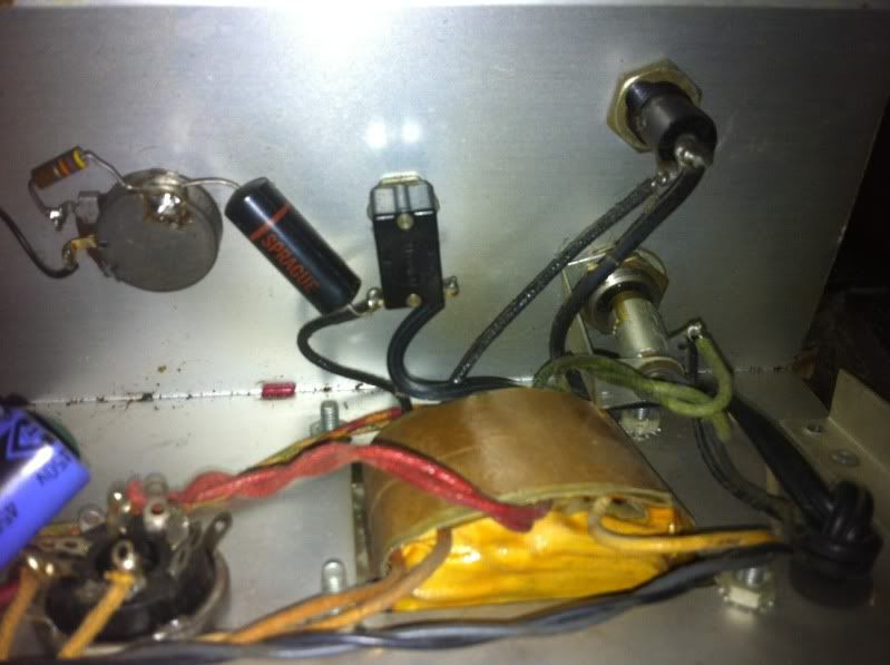
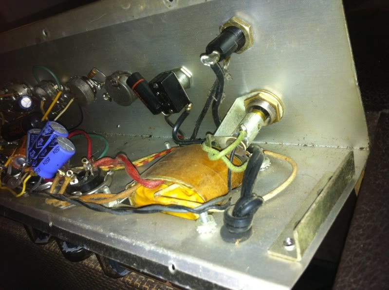
here are a few photos for reference.
[IMG:799:597]http://i109.photobucket.com/albums/n53/ ... photo1.jpg[/img]
[IMG:799:597]http://i109.photobucket.com/albums/n53/ ... photo2.jpg[/img]
gibson falcon ga 19 rvt 3 prong walkthrough HELP!
Moderators: pompeiisneaks, Colossal
-
martin manning

- Posts: 14308
- Joined: Sun Jul 06, 2008 12:43 am
- Location: 39°06' N 84°30' W
Re: gibson falcon ga 19 rvt 3 prong walkthrough HELP!
That will work, except solder the green ground wire to a ground lug and put that under the transformer bolt, and leave the green wire long so it would be the last thing to go if the cord were pulled out of the strain relief.
However,
1) The ground lug for the earth ground should have it's own dedicated attachment. If you don't mind drilling a hole in the chassis that would be better. I would do that as part of a proper installation of a grounded cord and not worry about it affecting the value of the amp.
2) As described, the hot line will go fuse-PT primary and the neutral will go switch-PT primary. The best arrangement is to have the hot go fuse-switch-PT primary, and the neutral going direct to the PT. That switches the hot so there is no line voltage after the switch when it is off and no line voltage after the fuse if it blows. That requires another tie point for the neutral and another hole in the chassis, though.
I also see there is a black Sprague cap going from the power switch to ground on the back of a pot. I'd remove that because if it fails shorted you will have line voltage on the chassis.

Re: gibson falcon ga 19 rvt 3 prong walkthrough HELP!
Martin,
How do you feel about an unused pin on the rectifier socket as the tie point for the line neutral and one side of the PT primary? Or just splice, solder, and cover with heat shrink?
Otherwise, in the interest of safety, I think drilling one tiny hole to mount the line ground (green) and another to mount a terminal strip aren't that big a deal.
Of all the old Gibson amps, The Falcon may be the most common. Production records say that 13,710 of this model was made between 1962 and 1967. Unless it is one of the 12 made in the last two years, it is not particularly rare.
Phil
-
martin manning
- Posts: 14308
- Joined: Sun Jul 06, 2008 12:43 am
- Location: 39°06' N 84°30' W
Re: gibson falcon ga 19 rvt 3 prong walkthrough HELP!
I'd vote for adding a terminal strip over the other options.
-
Cliff Schecht
- Posts: 2629
- Joined: Wed Dec 30, 2009 7:32 am
- Location: Austin
- Contact:
Re: gibson falcon ga 19 rvt 3 prong walkthrough HELP!
Am I seeing correctly that one side of the line voltage is going to the switch (say the hot side) and the other side is going to the fuse (cold side) so that the fuse is after the PT?
If that is so then I would rewire this power section (using a 3 pronger) with hot going to the tab coming out from inside the fuse holder (so that when you are changing fuses the touchable exposed metal inside won't shock you) and the outer tab part going to the switch. One side of the PT primary goes to the other side of the switch. Of course cut out the "death cap" as mentioned above. For the cold side just solder the other PT primary lead right to the cold wire and heatshrink.
The ground wire can go to the PT bolt but I'd consider soldering it onto one of the ground tabs on the rectifier socket. Two reasons for this: 1) you don't have to drill a new hole anywhere and 2) a soldered connection to the rectifier socket won't come loose with vibrations as the PT lugs can. The UL/CE standard is to have a hole right near the line input (be it a cable or an IEC jack) that you install a solder lug on (with the ground wire attached) and securely fasten with a screw and locknut. Nothing else is supposed to be connected to this lug, just the green wire from the IEC cable.
I know these amps aren't rare but they will be one day and if this one is fairly original then that's something else to take into account. I like how these sound stock FWIW, once you put in a better speaker and /slightly/ tweak the circuits they can really come alive.
Cliff Schecht - Circuit P.I.
Re: gibson falcon ga 19 rvt 3 prong walkthrough HELP!
If we were going to be particular about things, I'd rework the cap job while I was in there. Those two radial caps with their butts up in the air, anchored only by the leads to the caps is a problem looking for a place to happen.
As long as you will be adding a terminal strip (I guess you will), do it in a location that will let you use axial caps and hang them "properly."
It occurs to me that there was a brown paper can cap with a metal strap that was riveted to the chassis. Drill out the rivet if not already done. Presto, you don't need to create a new hole! Hopefully it's location is close enough to where it should be.
Re: gibson falcon ga 19 rvt 3 prong walkthrough HELP!
can someone breifly go over what a terminal strip is with me? this is sounding significantly more in depth than I thought originally.
1. will just drilling a hole anywhere in the chassis do or should it be somewhere specific?
2. When removing that "death cap" Should I first unload all the caps first?
3. When wiring the neutral int the transformers primaries, how do I know EXACTLY which wire to attach it to? I definately don't want to mess it up so I'm trying to be overly cautious.
Thanks again in a huge way. I'm getting more and more excited about this "simple" mod
Re: gibson falcon ga 19 rvt 3 prong walkthrough HELP!
1) Drill the hole for the ground wire near the entrance of the power cord.
But put it where you can easily work on it.
Solder a ground lug to the green ground wire. ( you can use a crimp on eyelet style if you wish, but I would still solder it.
Remember to leave some slack in the green wire as mentioned by Martin.
2) You can just snip the death cap out, there is only AC on it.
3) When you get the new three prong power cord it will have a black (hot), white (neutral) and green (ground).
The black is hot and should go to the fuse (the lug on the end), then from the fuse to the power switch.
The neutral (white) will go to one of the primary wires of the PT and the other PT wire goes to the power switch.
This is a terminal strip.
[img:250:250]http://www.newoldsounds.com/images/medium/PCS-3_MED.JPG[/img]
Notice the middle lug is connected to the mounting tab. Ordinarily you would not solder anything to that middle lug unless you wanted it grounded.
Tom
Don't let that smoke out!
Don't let that smoke out!