Issue With Bassman 5F6A Build

Fender Amp Discussion

Moderators: pompeiisneaks, Colossal

Post Reply
Guitarnut
Posts: 314
Joined: Sat Sep 04, 2010 11:25 pm

Re: Issue With Bassman 5F6A Build

Post by Guitarnut »

alvarezh wrote:30th from scratch? Yow are a candidate for a Master Builder spot at Fender. Very nice axe indeed.

Couple of questions:

1) One piece neck?

2) Could you give us some details on how you made (bought?) the "brand" decal?

Hope you solve your amp's problem soon.

Good week end to all.

Thanks Horacio! Guitars are where my true ability lies. I'm just muddling around trying to understand tube amps. They've always fascinated me.

The neck is a 2-piece. I've done one piece necks with vintage style truss rods but the dual action rods like I used in this neck don't work well with a skunk stripe...they've been known to push them out.

The decal was printed on an inkjet printer using water slide decal stock. A few coats of clear to seal the headstock, wet sand, buff and then apply the decal. Then 6 to 8 coats of clear to hide the edges. Wet sand again and buff. Done.

Peace,
Mark
User avatar
alvarezh
Posts: 461
Joined: Thu Oct 18, 2007 11:11 am
Location: Santo Domingo, D.R.

Re: Issue With Bassman 5F6A Build

Post by alvarezh »

Thanks Mark.

Good to know about the two way rod pulling the fretboard.

Thank you on the decal info also. I have worked on that with Testor decal paper so I am familiar. I can do a lot of things but painting and finishing (together with lead playing) I am really, really, bad. But yes, thanks again for the explanation.

Cheers!
Horacio

Play in tune and B#!
CHIP
Posts: 760
Joined: Sat Jan 05, 2008 4:35 am
Location: Down by the river

Re: Issue With Bassman 5F6A Build

Post by CHIP »

The guitar is a real beauty!
I think I'd stick with the 22 awg wire as Martin suggested, or 20awg. 600 v.
I think 18ga. is difficult to work with. Of course you should use it for the heaters.
Guitarnut
Posts: 314
Joined: Sat Sep 04, 2010 11:25 pm

Re: Issue With Bassman 5F6A Build

Post by Guitarnut »

alvarezh wrote:Thanks Mark.

Good to know about the two way rod pulling the fretboard.

Thank you on the decal info also. I have worked on that with Testor decal paper so I am familiar. I can do a lot of things but painting and finishing (together with lead playing) I am really, really, bad. But yes, thanks again for the explanation.

Cheers!
Happy to share the info with you.

Just to clarify, it's the walnut insert on the back of a one piece neck (skunk stripe) that can be pushed out by the dual action rods. The fretboards are fine with either single action or dual action rods. And to be honest, I've never seen an insert pushed out but have heard others experience.

Peace,
Mark
Guitarnut
Posts: 314
Joined: Sat Sep 04, 2010 11:25 pm

Re: Issue With Bassman 5F6A Build

Post by Guitarnut »

I added a few more clips of the Strat in the above post through an Epi BC30. It doesn't have as much clean headroom as the Blues Deluxe so even the clean is a bit grittier but I prefer the A5s on the dirty cut through this amp.

Peace,
Mark
User avatar
Reeltarded
Posts: 10189
Joined: Sat Feb 14, 2009 4:38 am
Location: GA USA

Re: Issue With Bassman 5F6A Build

Post by Reeltarded »

Even the originals come apart, way more than you might think...
Signatures have a 255 character limit that I could abuse, but I am not Cecil B. DeMille.
Guitarnut
Posts: 314
Joined: Sat Sep 04, 2010 11:25 pm

Re: Issue With Bassman 5F6A Build

Post by Guitarnut »

Reeltarded wrote:Even the originals come apart, way more than you might think...
You talking about sound clips, necks or amps? :wink:

Peace,
Mark
Guitarnut
Posts: 314
Joined: Sat Sep 04, 2010 11:25 pm

Re: Issue With Bassman 5F6A Build

Post by Guitarnut »

CHIP wrote:The guitar is a real beauty!
I think I'd stick with the 22 awg wire as Martin suggested, or 20awg. 600 v.
I think 18ga. is difficult to work with. Of course you should use it for the heaters.
Thanks Chip!

The 18awg is all I have on hand and the only store open around here on Sunday is the Shack...all their wire is 300V max. I may hit the local supply house tomorrow and see what I can find there.

Peace,
Mark
User avatar
martin manning
Posts: 14308
Joined: Sun Jul 06, 2008 12:43 am
Location: 39°06' N 84°30' W

Re: Issue With Bassman 5F6A Build

Post by martin manning »

Get the right stuff. An experienced builder can make do and have it come out looking good. Frst-timers don't need any extra challenges.

So Mark, I gotta ask. What does that guitar look like under the hood? Guitar wiring has it's own challenges, some not unlike an amp- tight quarters, skinny wires, low signal levels, and you wound your own p'ups too... I guess on a Strat you can do it all in the open on the back of the pickguard, except for the final connections to the output jack and ground.

Why did you go with turrets instead of eyelets for the Bassman? Was this a kit or did you gather-up the parts yourself?
User avatar
Reeltarded
Posts: 10189
Joined: Sat Feb 14, 2009 4:38 am
Location: GA USA

Re: Issue With Bassman 5F6A Build

Post by Reeltarded »

Guitarnut wrote:
Reeltarded wrote:Even the originals come apart, way more than you might think...
You talking about sound clips, necks or amps? :wink:

Peace,
Mark
Hah! Fender necks.
Signatures have a 255 character limit that I could abuse, but I am not Cecil B. DeMille.
Guitarnut
Posts: 314
Joined: Sat Sep 04, 2010 11:25 pm

Re: Issue With Bassman 5F6A Build

Post by Guitarnut »

martin manning wrote:Get the right stuff. An experienced builder can make do and have it come out looking good. Frst-timers don't need any extra challenges.

So Mark, I gotta ask. What does that guitar look like under the hood? Guitar wiring has it's own challenges, some not unlike an amp- tight quarters, skinny wires, low signal levels, and you wound your own p'ups too... I guess on a Strat you can do it all in the open on the back of the pickguard, except for the final connections to the output jack and ground.

Why did you go with turrets instead of eyelets for the Bassman? Was this a kit or did you gather-up the parts yourself?
Guitar wiring is far easier than what I'm dealing with in this amp project. Very thin wire, little heat required and very simple circuits by comparison. I can wire Les Pauls, Teles and Strats in my sleep.

I almost hate to mention where I bought the kit...starts with Mojo and ends with tone. But never again. I'm composing a letter to Andrew to express my dislike not only for his business model but for his lack of hands-on attention when there were problems. Isn't that what a sales manager does? I left messages on his voice mail but always received calls from Jason, who is a nice guy in a bad situation having to run interference for a system he doesn't agree with either.

Mojo is basically a cabinet shop who orders parts as needed. They're at the mercy of their suppliers. No parts from suppliers, no parts for customers. They still owe me 10ft of white wire.

"Inventory cost money and increases a companies tax burden"...well no s**t! Crappiest business model a company could have. Right or wrong, that's the impression I was left with.

Peace,
Mark
Guitarnut
Posts: 314
Joined: Sat Sep 04, 2010 11:25 pm

Re: Issue With Bassman 5F6A Build

Post by Guitarnut »

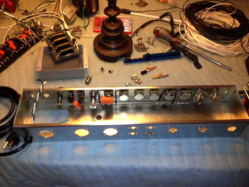
Well, I did it. I stripped the entire chassis and started in fresh. It's surprising how quickly they come apart compared to the time it took to put it together. :D

One change I made which was due to a rookie mistake, was to turn all the hardware around. I previously had the screws for the doghouse and OT on the outside and nuts on the inside. This really interfered with the placement on the board and made it next to impossible to remove the doghouse without removing the board.

[img:800:600]http://www.crenshawweb.com/bassman/build42.jpg[/img]

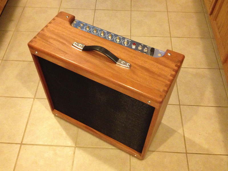
While I had it apart, I fit the chassis into the cab...the one thing I forgot to do before it weighed 15 lbs. Much easier this way.

[img:800:600]http://www.crenshawweb.com/bassman/build43.jpg[/img]

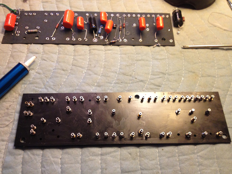
So, back to the rebuild. The first time around I was checking drawings, identifying parts, sorting out placement...just not focusing on the basics.

After some time with a solder sucker...love that thing...and then a wipe down with DNA and I'm ready to go.

[img:800:600]http://www.crenshawweb.com/bassman/build44.jpg[/img]

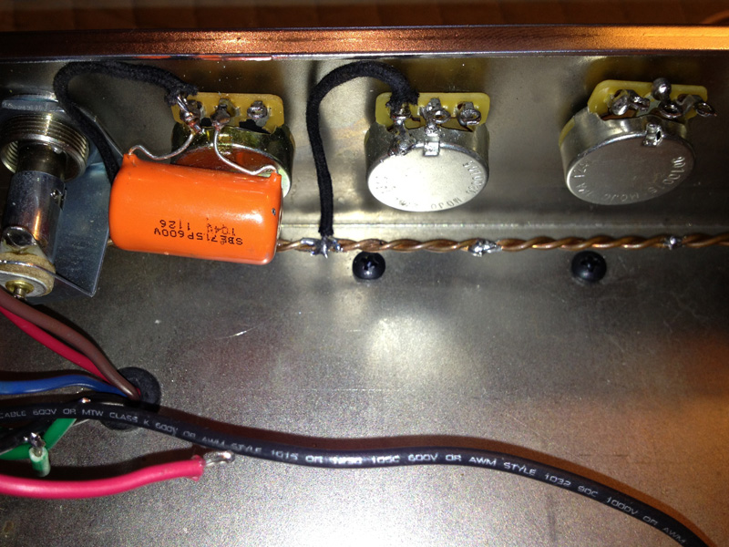
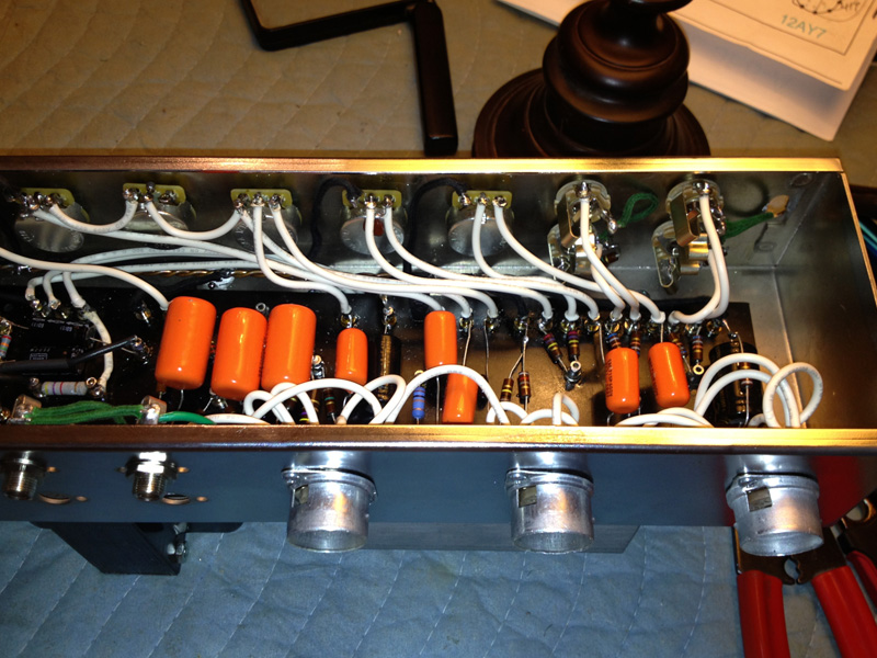
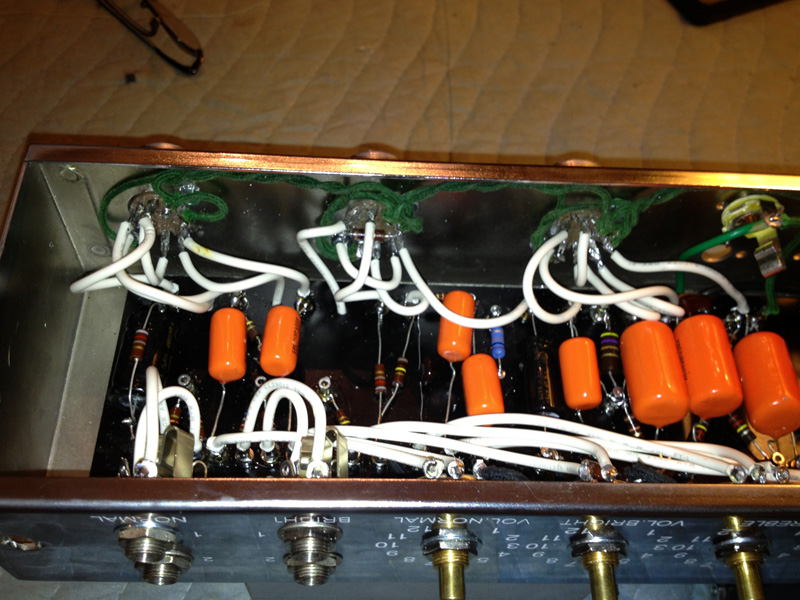
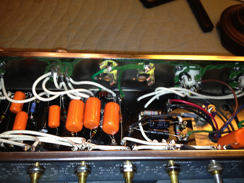
Here are some shots that I should have taken the first time around that might have helped with trouble shooting.

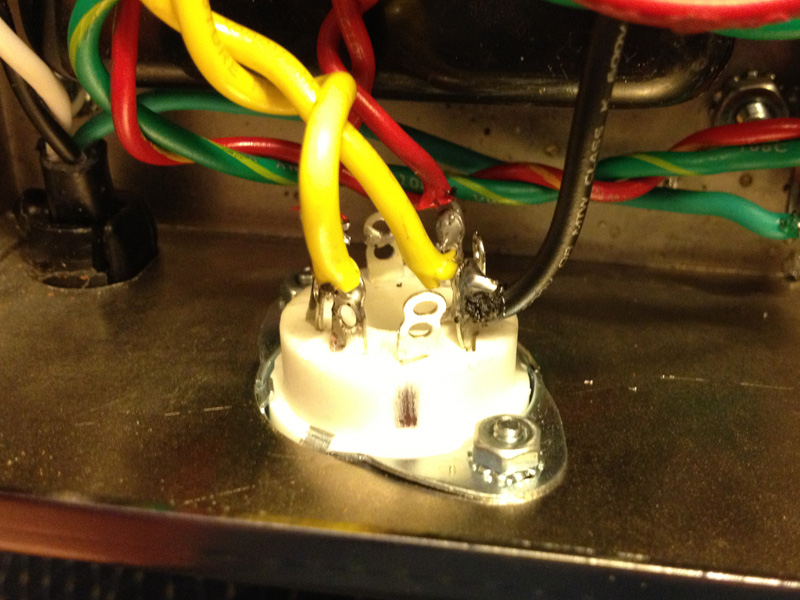
Ground bus that runs along the front of the chassis. Anchored at the PT mount and floating on the other end...help in place by ground wires. Gain stages, pots and power tubes are grounded here.

[img:800:600]http://www.crenshawweb.com/bassman/build47.jpg[/img]

[img:800:600]http://www.crenshawweb.com/bassman/build48.jpg[/img]

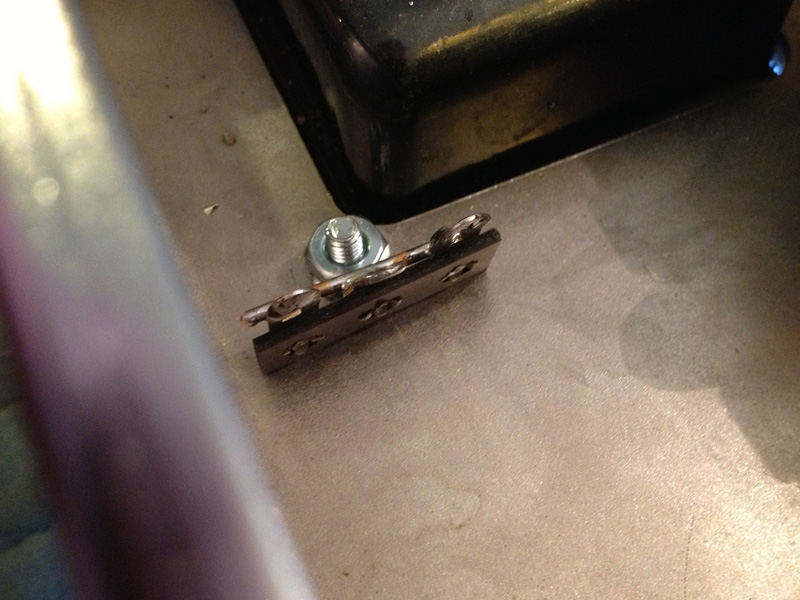
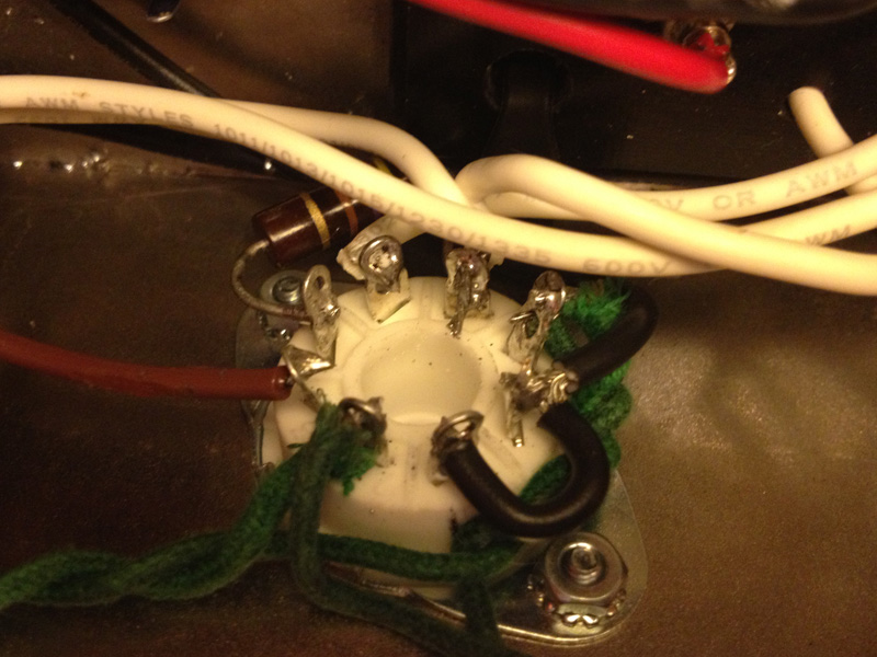
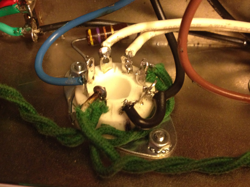
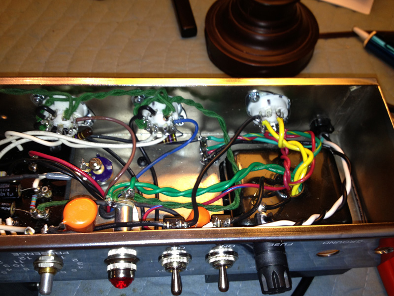
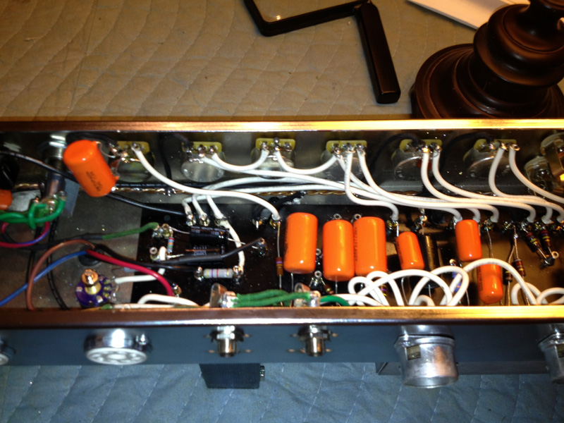
Terminal strip also on PT mount. Earth, PTcenter taps, OT and filter caps are grounded here.

[img:800:600]http://www.crenshawweb.com/bassman/build45.jpg[/img]

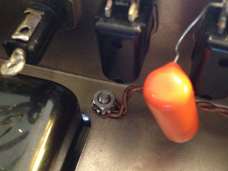
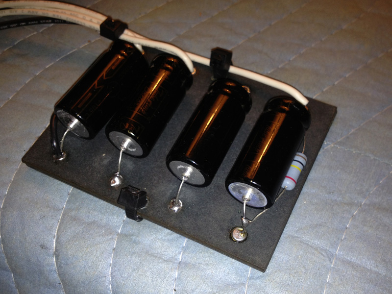
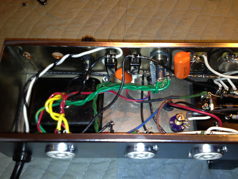
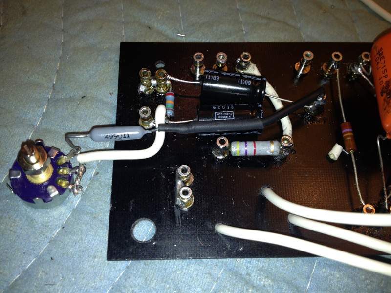
I added a 100K 2W bleed resistor to the filter caps.

[img:800:600]http://www.crenshawweb.com/bassman/build49.jpg[/img]

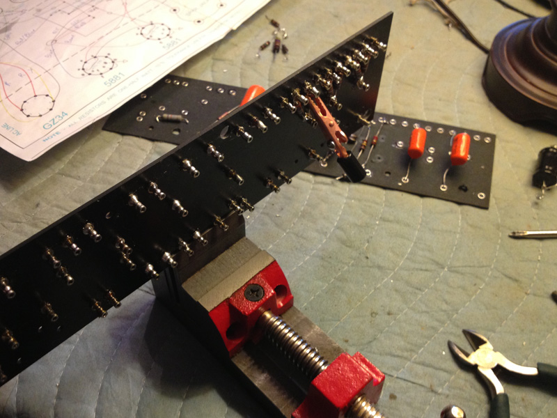
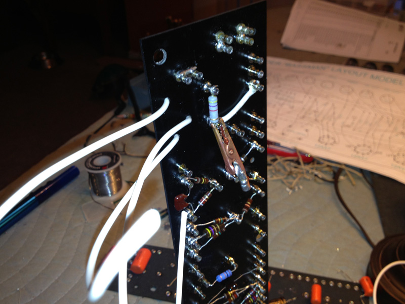
I also adopted the use of my Stew Mac nut and saddle vise. It's heavy enough to hold the fully loaded board without tipping but light enough to move around with ease. One of the struggles I had in round one of the build was not having 4 hands...not usually an issue wiring guitars. By letting gravity and heat sinks hold things in place, I could really focus on the solder joints.

[img:800:600]http://www.crenshawweb.com/bassman/build50.jpg[/img]

[img:800:600]http://www.crenshawweb.com/bassman/build51.jpg[/img]

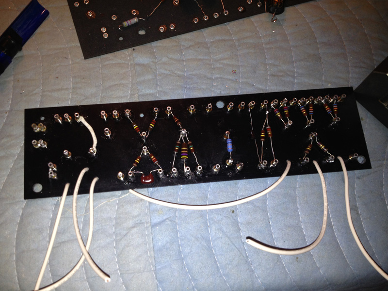
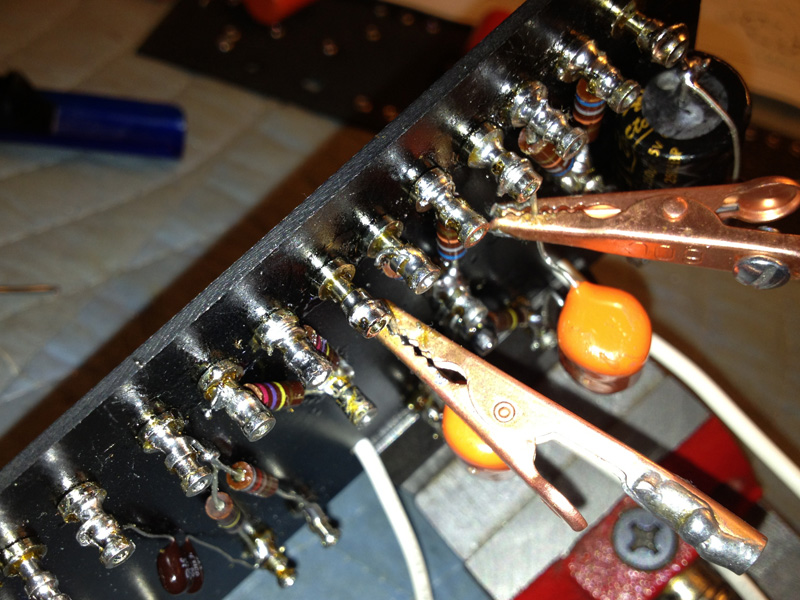
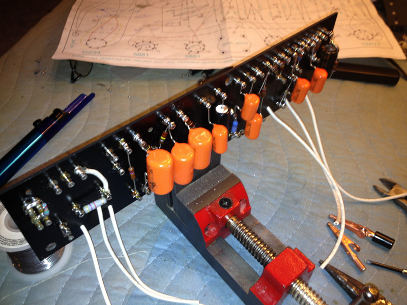
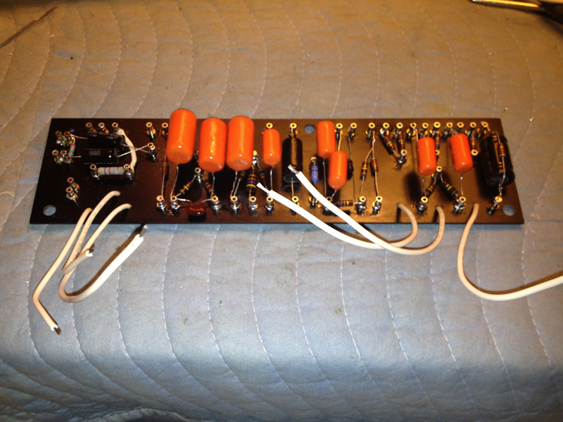
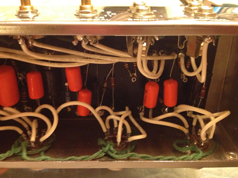
On the first build, I started at one end and just worked my way down. The large caps were a challenge when trying to tuck resistors under them. This time I did all the resistors first, keeping them low on the turrets. Then went back and added the caps keeping them on the upper slot of the turrets. It worked out great and was visually easier to reference what was where when I did a QC pass.

[img:800:600]http://www.crenshawweb.com/bassman/build52.jpg[/img]

[img:800:600]http://www.crenshawweb.com/bassman/build53.jpg[/img]

[img:800:600]http://www.crenshawweb.com/bassman/build54.jpg[/img]

Peace,
Mark
Last edited by Guitarnut on Mon May 06, 2013 5:29 pm, edited 1 time in total.
Guitarnut
Posts: 314
Joined: Sat Sep 04, 2010 11:25 pm

Re: Issue With Bassman 5F6A Build

Post by Guitarnut »

Some detail shots.

[img:800:600]http://www.crenshawweb.com/bassman/build55.jpg[/img]

[img:800:600]http://www.crenshawweb.com/bassman/build57.jpg[/img]

[img:800:600]http://www.crenshawweb.com/bassman/build58.jpg[/img]

[img:800:600]http://www.crenshawweb.com/bassman/build59.jpg[/img]

[img:800:600]http://www.crenshawweb.com/bassman/build60.jpg[/img]

[img:800:600]http://www.crenshawweb.com/bassman/build61.jpg[/img]

[img:800:600]http://www.crenshawweb.com/bassman/build62.jpg[/img]

[img:800:600]http://www.crenshawweb.com/bassman/build63.jpg[/img]

[img:800:600]http://www.crenshawweb.com/bassman/build64.jpg[/img]

[img:800:600]http://www.crenshawweb.com/bassman/build65.jpg[/img]

[img:800:600]http://www.crenshawweb.com/bassman/build66.jpg[/img]

I decided to go ahead and add the variable/fixed bias circuit that Dave over at Boot Hiil uses. I had ordered some replacement filter caps for the bias circuit and he kindly threw in the 47K pot and 5K 2W resistor.

[img:800:600]http://www.crenshawweb.com/bassman/build56.jpg[/img]

Peace,
Mark
Guitarnut
Posts: 314
Joined: Sat Sep 04, 2010 11:25 pm

Re: Issue With Bassman 5F6A Build

Post by Guitarnut »

It was pretty late when I wrapped up last and I was getting sleepy so I didn't spend too much time checking voltages. I did power up and checked AC on the PT and heaters, plugged in the rectifier and checked DC and all seems good. I have healthy voltages on all filter caps, plates, and the adjustable bias ran from -32v to -59v...IIRC.

I'll check and record everything this evening.

Peace,
Mark
Last edited by Guitarnut on Mon May 06, 2013 6:24 pm, edited 1 time in total.
User avatar
martin manning
Posts: 14308
Joined: Sun Jul 06, 2008 12:43 am
Location: 39°06' N 84°30' W

Re: Issue With Bassman 5F6A Build

Post by martin manning »

Well it will be interesting to see how it turns out this time. You have some unconventional lead dress there. Typically a ground buss is connected to the chassis at the input jack, and using transformer mounting bolts as ground points is not recommended. At the very least you should move the earth ground to a dedicated bolt. I don't know if you have grounded the input jacks to the buss, but I'd say don't. Since they are not isolated from the chassis that will make a ground loop. I think it would be okay if you ground the first stage cathodes to the input jacks, and let the jacks themselves be the chassis connection for the first stage.
Post Reply