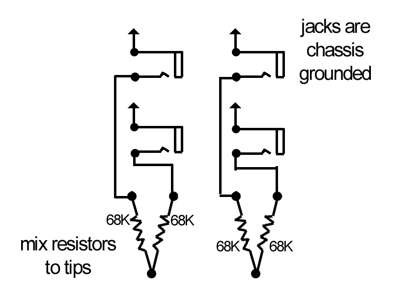
Since I'll be using this amp for playing guitar...one at a time is all I'm capable of...can I just simplify things by using standard jacks and hooking up the mix resistors like so?
[img:800:600]http://www.crenshawweb.com/bassman/input_jacks.jpg[/img]
Issue With Bassman 5F6A Build
Moderators: pompeiisneaks, Colossal

Re: Issue With Bassman 5F6A Build
You can hang them on the jacks, on a turret board, or on the tube sockets. The treatment you show is typical. I think I'd call them grid stoppers. An amp can be built without them. AFAIK, they are there to reduce noise.
Re: Issue With Bassman 5F6A Build
Phil_S wrote:...The treatment you show is typical.
Interesting. The Weber and Mojotone schematics use switching jacks.
Peace,
Mark
Last edited by Guitarnut on Thu May 02, 2013 12:02 am, edited 1 time in total.
Re: Issue With Bassman 5F6A Build
They're partly grid stops, but mostly to isolate the guitars from each other if you plug more than one in. You should maybe add 1M grid loads (don't have to, tho). But why are you fiddling with the established circuit? You're having trouble getting a by-the-book build to behave.
-
statorvane

- Posts: 568
- Joined: Thu May 11, 2006 3:28 pm
- Location: Upstate New York
Re: Issue With Bassman 5F6A Build
The way you have your schematic, the unused jack inputs aren't grounded when not in use. You'll get a lot of buzz that way. Use shorting jacks and wire them up like this:
http://www.18watt.com/files/high_and_lo ... tion_2.gif
http://www.18watt.com/files/high_and_lo ... tion_2.gif
Re: Issue With Bassman 5F6A Build
Excellent explanation. Thanks!statorvane wrote:The way you have your schematic, the unused jack inputs aren't grounded when not in use. You'll get a lot of buzz that way. Use shorting jacks and wire them up like this:
http://www.18watt.com/files/high_and_lo ... tion_2.gif
The way Mojotone has it drawn is confusing.
Peace,
Mark
-
martin manning

- Posts: 14308
- Joined: Sun Jul 06, 2008 12:43 am
- Location: 39°06' N 84°30' W
Re: Issue With Bassman 5F6A Build
V2 still looks ok, let's get V1 going first and then go after the PI. I'm wondering if there is a problem with the ground reference for V1a and b. I think I can see the 1M resistors on the input jacks, but verify that the jacks are wired like the picture below. I would put the 1M on the other side of the jacks, and I would run a wire tying all of the ground lugs together and connect that to the ground side of the V1 cathode cap and resistor on the board.
You do not have the required permissions to view the files attached to this post.
Re: Issue With Bassman 5F6A Build
I couldn't work with the Mojotone drawing so this ^ is the one I followed. I tied the grounds together but didn't take them to the cap/resistor. I'll add that jumper and see where we are.martin manning wrote:V2 still looks ok, let's get V1 going first and then go after the PI. I'm wondering if there is a problem with the ground reference for V1a and b. I think I can see the 1M resistors on the input jacks, but verify that the jacks are wired like the picture below. I would put the 1M on the other side of the jacks, and I would run a wire tying all of the ground lugs together and connect that to the ground side of the V1 cathode cap and resistor on the board.
Thanks as always,
Mark
Re: Issue With Bassman 5F6A Build
I verified the jacks are wired to the drawing your posted. Each pair of jacks had the grounds jumped together. I added a jumper from one bright jack to one normal and from there a jumper to the ground side cathode cap/resistor. Before powering up, I checked for continuity from the ground bus to ground tabs on all 4 jacks. And neg side of cap/resistor to ground. All good.
Powered up and no change in voltages. Pin 6 194v and pin 1 119v. Cathodes are at 3.3v. I checked the ground side of the cathode cap and it's at zero.
Here's a thought. The cathode cap is what Mojo called a bipolar. It's 2 caps set opposite of each other in one package. neg-pos-pos-neg. So it doesn't matter which way it installs. Could this be an issue?
Peace,
Mark
Last edited by Guitarnut on Thu May 02, 2013 2:28 pm, edited 2 times in total.
Re: Issue With Bassman 5F6A Build
A curiosity as I look over the numbers. I noticed that V2 pin 7 shows a high voltage compared to the other two 9 pin tubes. Is this because it's a cathode follower and it's voltage is taken from the plate of the previous stage vs from a coupling cap?
Peace,
Mark
Peace,
Mark
-
martin manning
- Posts: 14308
- Joined: Sun Jul 06, 2008 12:43 am
- Location: 39°06' N 84°30' W
Re: Issue With Bassman 5F6A Build
Bipolar is ok. Check the resistance across that cap resistor pair. You should see pretty close to 820 ohm. Do you know that the 12AY7 is good? You could put a 12AX7 in there temporarily to see if that changes anything.
-
martin manning
- Posts: 14308
- Joined: Sun Jul 06, 2008 12:43 am
- Location: 39°06' N 84°30' W
Re: Issue With Bassman 5F6A Build
Yes. There is no plate load so the plate is at B+, and the cathode will come up to a bit above the grid, which as you note is sitting at the plate voltage of the previous stage.Guitarnut wrote:A curiosity as I look over the numbers. I noticed that V2 pin 7 shows a high voltage compared to the other two 9 pin tubes. Is this because it's a cathode follower and it's voltage is taken from the plate of the previous stage vs from a coupling cap?
Peace,
Mark
Re: Issue With Bassman 5F6A Build
Thanks again Martin,martin manning wrote:Bipolar is ok. Check the resistance across that cap resistor pair. You should see pretty close to 820 ohm. Do you know that the 12AY7 is good? You could put a 12AX7 in there temporarily to see if that changes anything.
Thru this process I've swapped tubes in both V1 and V3. I've had 2 different 12ay7's and a 12ax7 in V1. At least 3 different 12ax7's in V3.
The R you wanted me to check is 790.
If you have other ideas please post them but I have to go to work and deal with some difficult clients to get my mind off of this.
More this evening.
Peace,
Mark
Re: Issue With Bassman 5F6A Build
The cathode follower is a current amp instead of a voltage amp? It doesn't appear to be amplifying voltage.martin manning wrote: Yes. There is no plate load so the plate is at B+, and the cathode will come up to a bit above the grid, which as you note is sitting at the plate voltage of the previous stage.
Peace,
Mark
-
Reeltarded

- Posts: 10189
- Joined: Sat Feb 14, 2009 4:38 am
- Location: GA USA
Re: Issue With Bassman 5F6A Build
Here, Mark..
http://www.ampbooks.com/home/classic-ci ... ltage-amp/
Two things I want to do in this life.
1. Discover something astronomical that freaks people out.
2. Figure out what the problem with this build is before the experts do.
My brain has been boiling for long enough to call it soup by now.
-Miles
http://www.ampbooks.com/home/classic-ci ... ltage-amp/
Two things I want to do in this life.
1. Discover something astronomical that freaks people out.
2. Figure out what the problem with this build is before the experts do.
My brain has been boiling for long enough to call it soup by now.
-Miles
Signatures have a 255 character limit that I could abuse, but I am not Cecil B. DeMille.