I think my power tranny is blown. The wires going to the mains selector is the primary and they are black, orange and yellow. Theres another yellow wire on the center on the selector. If I measure the resistance from any of the wires to ground I get nothing. From black to yellow 6.6ohms from black to orange 5.7ohms orange to yellow 1.9ohms.
Is this normal or am I doing this wrong? I don't have a mains fuse in the holder when I'm testing.
The amp blows the mains fuse immediately on startup even with the tubes pulled. The rectifier diodes measure good and so do the filter caps.
Testing the PT in my 1987x
Moderators: pompeiisneaks, Colossal
Re: Testing the PT in my 1987x
I suggest disconnecting all secondaries of PT ( make sure you tape them for safety) and try with a fastblow fuse (1A). If it blows you have a problem with the PT, if not you have a problem in the circuit.

Re: Testing the PT in my 1987x
If it is shorted, it will blow fuses. Is there some other reason that suggests it is the PT?
Before jumping off on a bunch of unnecessary work, have you tried to power up the amp with all the tubes pulled out? For the most part, this "unloads" the transformer, except for maybe the pilot light.
Assuming it is the PT you need to test, I do not think that measuring from any of the primary leads to ground tells you much of anything. Unless I've misunderstood what you did, I think you need to try again. Think about this...the primary side of the PT is isolated from the chassis, otherwise the chassis would be hot with the wall supply every time you plug it in!
The primary should be relatively easy to "ohm". Just hook your meter to the plug (obviously not connected to the wall supply) and see what you get across the two prongs in each of the three selectable positions. (If a 3-prong, ignore the redundant ground.) Yes, the lead of wire between the amp and the plug adds something, but it is not important for this test. I think something under about 50 ohms is about right for the primary side of a PT and those low readings you posted seem appropriate to me.
Assuming you have continuity on the all 3 of the primary selections, I would then want to test the secondary windings. To do this, pull all the tubes and check the ohms on the HT secondary. It should be roughly the same from each outer leg to the CT. You will need to lift the CT from ground for this test. You can just clip the meter onto the tube socket pin for each of the outer legs. If not reasonably close (these won't be precisely identical), that is a good sign. If not close, chances are the secondary is shorted.
I might want to test the filament winding(s), too, but let's get this far, first.
Do this much and post what you find. Also answer the opening questions. From there, what you say will suggest the next step.
-
War Admiral
- Posts: 27
- Joined: Tue Apr 01, 2008 4:56 pm
Re: Testing the PT in my 1987x
Thanks Phil. The amp blows the fuse immediately on startup with no tubes. I just tested between the 2 prongs on the mains input(plug) and I have 2.9ohms(110v) 8.2ohms(220v) 9.3ohms(230v) with the ac and standby switches on.(not plugged in of course)Phil_S wrote:If it is shorted, it will blow fuses. Is there some other reason that suggests it is the PT?
Before jumping off on a bunch of unnecessary work, have you tried to power up the amp with all the tubes pulled out? For the most part, this "unloads" the transformer, except for maybe the pilot light.
Assuming it is the PT you need to test, I do not think that measuring from any of the primary leads to ground tells you much of anything. Unless I've misunderstood what you did, I think you need to try again. Think about this...the primary side of the PT is isolated from the chassis, otherwise the chassis would be hot with the wall supply every time you plug it in!
The primary should be relatively easy to "ohm". Just hook your meter to the plug (obviously not connected to the wall supply) and see what you get across the two prongs in each of the three selectable positions. (If a 3-prong, ignore the redundant ground.) Yes, the lead of wire between the amp and the plug adds something, but it is not important for this test. I think something under about 50 ohms is about right for the primary side of a PT and those low readings you posted seem appropriate to me.
Assuming you have continuity on the all 3 of the primary selections, I would then want to test the secondary windings. To do this, pull all the tubes and check the ohms on the HT secondary. It should be roughly the same from each outer leg to the CT. You will need to lift the CT from ground for this test. You can just clip the meter onto the tube socket pin for each of the outer legs. If not reasonably close (these won't be precisely identical), that is a good sign. If not close, chances are the secondary is shorted.
I might want to test the filament winding(s), too, but let's get this far, first.
Do this much and post what you find. Also answer the opening questions. From there, what you say will suggest the next step.
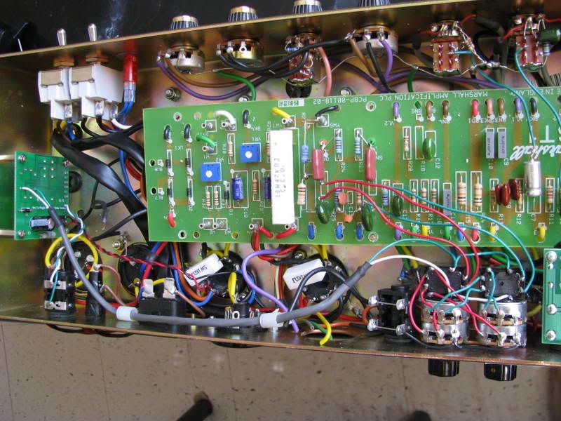
Secondary, red, black and brown(centertap) I clipped the brown from ground and measured the red and black from centertap going to pin 2 and pin 7 respectively. Red(.4ohms) black(.4ohms) I have wires coming off these pins to power my relay for my footswitchable dual PPIMV's. I hope it doesn't interfere with the readings.
Heres a pic:
[IMG:800:600]http://i46.photobucket.com/albums/f144/ ... 87x001.jpg[/img]
Re: Testing the PT in my 1987x
I would agree this is a bad sign.War Admiral wrote:Thanks Phil. The amp blows the fuse immediately on startup with no tubes.
These seem like reasonable readings. I'm in USA and have three bone-pile PT's right now that are all 115v type and ohm on the primary between roughly 5 ohms and 20 ohms. It is also good that you have a progression that makes sense.I just tested between the 2 prongs on the mains input(plug) and I have 2.9ohms(110v) 8.2ohms(220v) 9.3ohms(230v) with the ac and standby switches on.(not plugged in of course)
These are also encouraging. Marshall's are known to have very low Z secondary windings. The symmetry is a good sign.Secondary, red, black and brown(centertap) I clipped the brown from ground and measured the red and black from centertap going to pin 2 and pin 7 respectively. Red(.4ohms) black(.4ohms)
At this point, if you really suspect the PT, I would try to test it out of circuit. For this, unsolder all connections on the secondaries. This includes filament winding(s). Put a 1A fuse in, and turn it on. Check secondary output voltage for reasonableness if the fuse doesn't blow.
If it blows the fuse, I think it is safe to assume your PT has bought the farm. I would want to know why. Otherwise, you could potentially replace it and have the same happen to the new one.
If by a 1987x, you mean a JTM 45, then the HT secondary should be around 350-0-350. There should also be 5v and 6.3v filament windings. If I am wrong about the model, then you need to find the right info, but something between 300 and 400 VAC on an unloaded secondary (measured to the CT) or 700-800VAC total is certainly reasonable.
I admit to being out of my depth on this one. I'm an amateur. If in doubt, lift the connections and Ohm-it again.I have wires coming off these pins to power my relay for my footswitchable dual PPIMV's. I hope it doesn't interfere with the readings.
You don't need to ask me how I know about a blown PT. Just take my word for it.
-
War Admiral
- Posts: 27
- Joined: Tue Apr 01, 2008 4:56 pm
Re: Testing the PT in my 1987x
I got a light bulb and I'm going to jump the mains fuse holder with it without the fuse. I'll disconnect the secondary wires and fire it up and see how bright the light shines.
If its still bright with the secondary unhooked, I'll just start unhooking things until the light dims. What would be a good order of elimination if unhooking the secondary of the PT doesn't dim the light? Secondary of the OT? Rectifier diodes? Caps?
Thanks guys.
If its still bright with the secondary unhooked, I'll just start unhooking things until the light dims. What would be a good order of elimination if unhooking the secondary of the PT doesn't dim the light? Secondary of the OT? Rectifier diodes? Caps?
Thanks guys.
-
War Admiral
- Posts: 27
- Joined: Tue Apr 01, 2008 4:56 pm
Re: Testing the PT in my 1987x
As soon as I hit the standby, it goes through the rectifier, comes out DC and into the first filter cap and then we would be dealing with the HT fuse I guess.
PT secondary, I disconnect brown wire which is grounded(CT) and the 2 heater filaments(black and red) and I leave 2 red wires going to the standby and the black ground wire connected but I leave the standby in the open position. Turn the AC switch on.
If the light is bright(short) its definitely the PT right? What else would blow just the mains fuse?
You have the mains input and the voltage selector in that circuit and thats it.
Re: Testing the PT in my 1987x
Hmmm....what do you mean by black ground wire?
There should be two primary leads that draw power from the a/c line. Usually, those are black. Yours is a multi tap primary, so focus on the two that are appropriate. Anyway, neither is grounded, unless you are referring to the neutral side of the wall supply. Of course, that's grounded back at the service box.
I agree, a bright light indicates a short. The standby in open position (circuit broken) typically still allows the first filter cap to charge but that is defeated by pulling the rectifier tube. So, I'd agree with you. The light bulb in series is a time tested method. I should have thought of it.
If you suspect the voltage selector switch, you would benefit from lifing those connections and taking it out of the loop. If the PT is bad, you'll be clipping those anyway. Little to lose, much to gain?
-
War Admiral
- Posts: 27
- Joined: Tue Apr 01, 2008 4:56 pm
Re: Testing the PT in my 1987x
Phil, I was talking about the secondary wires on the PT. I have red, black and brown which goes to the heaters(red and black) pins 2 and 7 respectively and the brown which goes to the ground. Then I have 3 smaller wires(2 red which go to the standby and another black that goes to ground)
Re: Testing the PT in my 1987x
It sounds to me like you have one center tapped filament winding, red-brown-black, and one HT secondary winding red-black-red. Assuming that's right, the brown and black are the center taps and, yes, these are supposed to be grounded for proper operation of the amp. For testing purposes, you must lift the center taps from ground.
You say the filament winding goes to pins 2 & 7. That would be the power tubes, either KT66 or EL34? (same pin out, doesn't matter which type)
I am looking at the one picture you provided. There are 4 diodes at the edge of the board. The input to the diodes should be the two black wires on the side where the power switches are. You need to disconnect the diodes. Follow those black wires back and see if there is another place to disconnect them. Maybe there are some "fast-on" connectors that can be pulled. In any case, these connections from the PT to the diodes need to be lifted and these two black wires should trace back to the red-red HT secondary outer legs.
If, as you say, the standby controls these diodes, then it is OK to leave the switch in the open or off position. Somehow, that doesn't ring true to me. Normally, the standby is placed after the first filter cap, which allows that cap to charge when you close (on position) the power switch.
Put your volt meter across the red-red and you should get 700vac, give or take maybe 50v. I don't know what this amp is supposed to be working with.
Then, on the outer legs of the filament winding, across red-black, you should see 6-7vac. (You can leave these soldered to pins 2 and 7.)
If you see this sort of voltage on the secondary (provided you get this far), there is probably nothing wrong with your PT.
Also, using the light bulb limiter, should you be fortunate and get a dim bulb, you will know before you even check secondary VAC that the PT is OK.
-
War Admiral
- Posts: 27
- Joined: Tue Apr 01, 2008 4:56 pm
Re: Testing the PT in my 1987x
O.K. I took the old mains fuse out and hooked up a light bulb to the mains fuse holder. I disconected the heaters and its center tap. I left the standby in the open position since the red wires are fed to there before they go to the rectifier diodes.
The light is still bright. PT fried?
The light is still bright.
Re: Testing the PT in my 1987x
I agree that a bright light is a bad sign. I'd want to confirm that you've got no output on the secondaries or inappropriate output. Be sure to lift the center tap on all windings. Put your volt meter across the two red wires.
-
War Admiral
- Posts: 27
- Joined: Tue Apr 01, 2008 4:56 pm
Re: Testing the PT in my 1987x
Hey Phil. I lifted the ct of the 2 red wires and measured across the the 2 lugs where the red wires are connected on the standby and I have 21 VAC.
-
War Admiral
- Posts: 27
- Joined: Tue Apr 01, 2008 4:56 pm
Re: Testing the PT in my 1987x
I salvaged a 1202-164 Drake PT but its not the same colour code as the Dagnall that was in my 1987x. Heres a pic of my ''new'' PT. I want to bypass the voltage selector and just wire it up for 120 vac. I can just put the brown(120V) wire directly on the AC switch on the lug beside the blue(common) lug right and just heat shrink all of the other taps right? The AC input is still fused on the top 2 lugs of the AC switch(looking from the bottom of the chasis of course)
You do not have the required permissions to view the files attached to this post.
-
War Admiral
- Posts: 27
- Joined: Tue Apr 01, 2008 4:56 pm
Re: Testing the PT in my 1987x
Well it looks like it was the secondary of the PT. I wired up the primary of the new one and then jumped the bias supply on one of the high voltage wires from the standby on the secondary with the ct lifted and no bright light.
I measured across the 2 high voltage wires and I get 566 VAC where as before with the old tranny at the same setup I got 21 VAC and a bright light.
Thanks for taking me through this as it was my first time and now added this to my ongoing knowledge about amplifiers.
One last question, I bypassed the voltage selector on the primary by placing the common blue wire on the AC switch like it was before but I bypassed the selector with the 120 VAC tap (brown) straight to the other lug of the AC switch. I heat shrunk the remaining taps(100, 220, 230, 240)
I will ground the heater ct and the high voltage ct like before on the secondary. Is this O.K.? I won't be playing in Europe any time soon with this amp so.....