CtG electronics FCBN 51B question
Moderators: pompeiisneaks, Colossal
-
dbchamblee
- Posts: 5
- Joined: Wed Dec 24, 2014 8:53 pm
CtG electronics FCBN 51B question
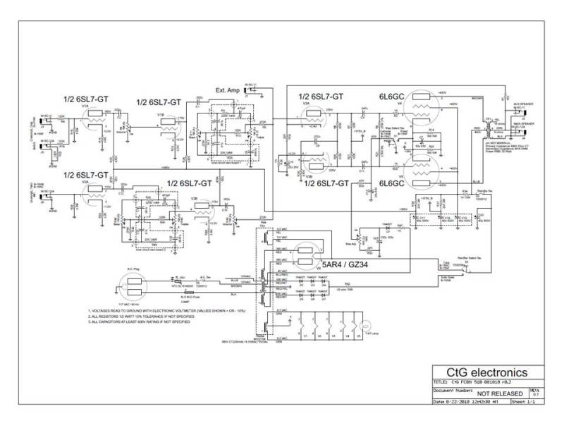
In looking at the schematic of this amp, I noticed that capacitors C13 and C23 in the cathode bias circuit are backwards with the positive side connected to ground. Is this right? The original Ampeg B-15NB schematics show a 50uF inserted correctly. The schematic is here: http://ctgelectronics.weebly.com/upload ... 5_orig.jpg
Re: CtG electronics FCBN 51B question
Can you post a higher resolution schematic?
Tom
Don't let that smoke out!
Don't let that smoke out!
Re: CtG electronics FCBN 51B question
The cathode bypass cap in that schematic has it's negative lead connected to ground just like a B15.
But this amp can operate with fixed bias or cathode bias and...
The caps you mentioned are part of the fixed bias circuit. Positive end should connect to ground for those.
But this amp can operate with fixed bias or cathode bias and...
The caps you mentioned are part of the fixed bias circuit. Positive end should connect to ground for those.
-
dbchamblee
- Posts: 5
- Joined: Wed Dec 24, 2014 8:53 pm
Re: CtG electronics FCBN 51B question
Structo, that's the highest resolution on their website. If you save it as a pdf and then open it in a viewer you can zoom in. After a little more research I have seen other schematics with a similar setup I'm just not used to seeing electrolytic caps used reverse polarity. I thought they'd blow. I admit I don't totally understand what's going on in this circuit. I assume the caps must be seeing a voltage that's negative with respect to ground.
-
JazzGuitarGimp

- Posts: 2357
- Joined: Mon Jul 23, 2012 4:54 pm
- Location: Northern CA
Re: CtG electronics FCBN 51B question
From the looks of it (low resolution schematic), I'd say the diode in the bias supply is drawn backwards. Yes, the bias supply cap is seeing a negative voltage with respect to GND.
Lou Rossi Designs
Printed Circuit Design & Layout,
and Schematic Capture
Printed Circuit Design & Layout,
and Schematic Capture

Re: CtG electronics FCBN 51B question
I have to say that I don't really like that solution.
Everytime you switch from fixed to cathode bias, you'll abruptly ground a cap charged with minus fiftysomething volts.
Everytime you switch from fixed to cathode bias, you'll abruptly ground a cap charged with minus fiftysomething volts.
-
dbchamblee
- Posts: 5
- Joined: Wed Dec 24, 2014 8:53 pm
Re: CtG electronics FCBN 51B question
roberto, I don't think you're supposed to change modes with the amp powered up, at least I wouldn't recommend it.
Re: CtG electronics FCBN 51B question
I agree, but a good design has to prevent possible actions that can cause reliability issues.
Re: CtG electronics FCBN 51B question
I built this circuit for a customer. The amp came out great and sounded quite nice- but I have to say I am not a Bass guy but believe the new owner when he tells me its sounding great.
If you want to check it out I have pictures of the build posted here:
https://www.facebook.com/media/set/?set ... 972&type=1
If you want to check it out I have pictures of the build posted here:
https://www.facebook.com/media/set/?set ... 972&type=1
Frugal Amps