How to verify solder joints
Moderators: pompeiisneaks, Colossal
How to verify solder joints
At the end of the build, how would you find out if you had any bad solder joints?
-
Prairie Dawg
- Posts: 156
- Joined: Sun Jan 10, 2010 2:19 am
- Location: Windsor Heights, Iowa
Re: How to verify solder joints
Your amp wouldn't work right?
If you believe in coincidence you're not looking close enough-Joe leaphorn
Re: How to verify solder joints
Well it may work. But fail at a gig or something. I'm not very good at soldering. Wondering if it's worth reflowing all the joints now that I'm not rushing and thinking about the circuit. Reflowing only joints that look off. Etc.
-
Leo_Gnardo

- Posts: 2585
- Joined: Thu Sep 27, 2012 1:33 pm
- Location: Dogpatch-on-Hudson
Re: How to verify solder joints
Even new amps from major manufactureres do that...wsaraceni wrote:Well it may work. But fail at a gig or something. - - - - -Reflowing only joints that look off. Etc.
Yes inspect, poke with chopstick, tug on wires, touch up anything that looks dicey. Beware of oversoldering and winding up with metal where you don't want it.
Sometimes it's good to have a knowledgable friend scan it for you too. A "fresh set of eyes" will often catch something that you missed. I've had people bring in amps where just one solder joint was missed. By the factory. In the 60's. At Fender. Also at McIntosh (!?!) not the computer. Rare but it does happen. How long people put up with an intermittent, and all it takes is a few seconds with the iron to fix it.
Last edited by Leo_Gnardo on Wed Aug 14, 2013 7:06 pm, edited 1 time in total.
down technical blind alleys . . .

Re: How to verify solder joints
and only 3 months to find it..How long people put up with an intermittent, and all it takes is a few seconds with the iron to fix it.

Re: How to verify solder joints
Look at them with lots of light and some maginification from different angles
and chopstick em real good
and chopstick em real good
Re: How to verify solder joints
Personally, I think a person should carefully observe the solder joint at the time of soldering it before moving on to the next joint.
A good solder joint is achieved by using a iron that is at the correct temperature for the soldering task at hand.
That is, the solder should melt quickly once the iron is applied to the joint.
I keep my iron around 650F to 700F.
Sometimes less if the item being soldered is small.
The material being soldered should be clean, (no oxide) and secured mechanically before adding solder to it.
One of the biggest mistakes I see novices make is not to clean, then tin the iron tip with fresh solder before soldering a joint.
Whether you use a damp sponge or a brillo pad type cleaner, clean the tip, then add some solder to the tip.
This solder on the tip will transfer the heat much better than a clean dry tip.
When soldering don't apply the solder wire to the iron but rather the joint being soldered.
This achieves a wetting action with the solder flowing into the joint.
Then pull the solder away, then the iron.
This should all take place in just a few seconds.
The critical point is when the solder in setting up or hardening.
Any movement of the wires or object being soldered can cause a cold joint/ dry joint, that does not conduct very well.
I like using eutectic solder which is 63% tin (Sn) and 37% lead (Pb)
It has a narrower molten range and sets faster than the traditional 60/40 solder.
A cold or dry solder joint is usually rough/ crystalized, not shiny looking.
Another example of a cold joint is when the component lead appears to be isolated from the joint or pad.
When in doubt, touch up the joint with some fresh solder.
COLD JOINT
[img:206:110]http://www.co-bw.com/Images_DIY/601-44.gif[/img]
[img:433:512]http://store.curiousinventor.com/media/ ... amount.jpg[/img]
Bad joints
[img:220:198]http://upload.wikimedia.org/wikipedia/c ... tellen.jpg[/img]
Tom
Don't let that smoke out!
Don't let that smoke out!

Re: How to verify solder joints
I realize this is not only what looks like a cold joint just visually, but additionally bad... What causes the green corrosion? If I'd venture a guess, it's improper cleaning prior to soldering. Yeah? (The green wire directly center on the brass plate.)
You do not have the required permissions to view the files attached to this post.
-
Leo_Gnardo
- Posts: 2585
- Joined: Thu Sep 27, 2012 1:33 pm
- Location: Dogpatch-on-Hudson
Re: How to verify solder joints
That green could be some funky flux, lets hope not acid flux. Green probably means there's some copper oxide or sulfide/sulfate. Occasionally I've found old plastic-insulated wired dripping green gooey crud - of unknown composition.Meat&Beer wrote:I realize this is not only what looks like a cold joint just visually, but additionally bad... What causes the green corrosion? If I'd venture a guess, it's improper cleaning prior to soldering. Yeah? (The green wire directly center on the brass plate.)
One customer uset to tell me his amp was "into mittens."
down technical blind alleys . . .
-
Luthierwnc

- Posts: 998
- Joined: Sat Feb 18, 2006 10:59 am
- Location: Asheville, NC
Re: How to verify solder joints
At one point I thought I could be efficient and tie-off several joints and then solder them at the same time. Now I do every one individually. That's one. Two is to reflow a little solder so they look like the pics Tom just posted. I use Cardas solder and it flows a lot better than some.
Three is maybe not necessary but when I finish primary soldering (should be all done if I did it all right) I avoid the temptation to fire it up and let an amp sit overnight. Then I check all the connections and values against the schematic instead of the layout diagram. I've got a good meter and I want a dead short between connections. First I check all ground points for continuity and ground loop potentials. Then the rest of the values.
Finally, take a look at the gut shot of a Dr Z amp. He uses a blob of red something on each joint after it has been checked. I don't do that but it can't hurt. I do use a red Sharpie on the schematic after each point. Do that enough and it looks like it has the measles.
One thing to be careful of is too much solder dripping down from the lug or turret -- especially if you have been substituting values in the tweaking stage. When I can, I bolt the board down last so I can check the bottom for solder stalactites or long leads that could ground or short. Since most solder joints are close to the edge of the board, curved-nose hemostats (which have lots of other uses) are great to reach under and comfirm there's nothing but air. Sometimes that is hard because the wires hold it down pretty close. Whether I can or can't, I do check the joints on the rail for continuity to ground after it is bolted down to reduce excitement during the spark test.
That's maybe more than you were looking for but I have a practical lesson for each step sh
sh
Three is maybe not necessary but when I finish primary soldering (should be all done if I did it all right) I avoid the temptation to fire it up and let an amp sit overnight. Then I check all the connections and values against the schematic instead of the layout diagram. I've got a good meter and I want a dead short between connections. First I check all ground points for continuity and ground loop potentials. Then the rest of the values.
Finally, take a look at the gut shot of a Dr Z amp. He uses a blob of red something on each joint after it has been checked. I don't do that but it can't hurt. I do use a red Sharpie on the schematic after each point. Do that enough and it looks like it has the measles.
One thing to be careful of is too much solder dripping down from the lug or turret -- especially if you have been substituting values in the tweaking stage. When I can, I bolt the board down last so I can check the bottom for solder stalactites or long leads that could ground or short. Since most solder joints are close to the edge of the board, curved-nose hemostats (which have lots of other uses) are great to reach under and comfirm there's nothing but air. Sometimes that is hard because the wires hold it down pretty close. Whether I can or can't, I do check the joints on the rail for continuity to ground after it is bolted down to reduce excitement during the spark test.
That's maybe more than you were looking for but I have a practical lesson for each step
-
martin manning

- Posts: 14308
- Joined: Sun Jul 06, 2008 12:43 am
- Location: 39°06' N 84°30' W
Re: How to verify solder joints
Brass is an alloy of copper and zinc. I'm guessing that the heat from the soldering exposed some copper, which has been corroded by flux residue.Meat&Beer wrote:What causes the green corrosion?
-
vibratoking
- Posts: 2640
- Joined: Tue Nov 10, 2009 9:55 pm
- Location: Colorado Springs, CO
Re: How to verify solder joints
What green corrosion? All I can see is that ugly connection from shield to shield.
Re: How to verify solder joints
Yea, it may not be pretty, but it's functional. No? Am I doing something wrong here? There is a lot of shielded wire in this amp, it's a really big two channel high gain one.vibratoking wrote:What green corrosion? All I can see is that ugly connection from shield to shield.
I'm just now able to get back into it, (Over a month off from it) I have a couple issues I have to debug. ...And the big one is ground. Perhaps I can be directed to a "Do and Don't" about shielded wire somewhere?
This is my first amp, but under the wing of a great dude that's been building them since he was a kid. Still, not everyone has all the answers.
Re: How to verify solder joints
Martin is right, the brass, being an alloy will turn green over time and especially with fluctuations in humidity (which you get every time your amp fires up/cools down).
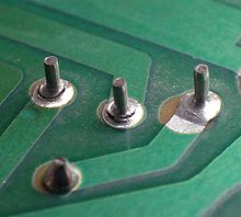
Great photos Structo!
I hate having to inspect the pin through/paddle solder type of PCB...even when the pin has the right amount of solder, if the pin itself is not heated enough the joint can be cold. I try to look for telltale pinholes/airholes in the surrounding solder (with high magnification). If I find cold joints in a board like that I usually re-solder the whole line of pins.
https://www.facebook.com/trialbyfirerocks
Be sure your tinfoil hat has a good low impedance ground.
Be sure your tinfoil hat has a good low impedance ground.
-
vibratoking
- Posts: 2640
- Joined: Tue Nov 10, 2009 9:55 pm
- Location: Colorado Springs, CO
Re: How to verify solder joints
It may be functional now, but for how long? You are using solder to make an electrical connection, which is good. You are also trying to make the electrical connection withstand mechanical stress, which is not so good IME. That is not a mechanically robust connection and why I frowned at it. Also, the solder looks like it's sitting on top of the shield and not wicked into it.Yea, it may not be pretty, but it's functional. No? Am I doing something wrong here?...
Sorry to be the bearer of bad news, but that's not a good solution. If that connection is absolutely required for good amp performance then your amp will fail to perform sooner or later. You need to provide a mechanical support and then make the electrical connection. I agree, we are all learning.