I am working on an amp today with something I have not seen before.
There is one preamp tube, and two output tubes (and a rectifier).
The output stage is push-pull, cathode biased.
At first glance I wondered how the output tubes could be driven with signals 180 deg out of phase from eachother being that the amp only had one preamp tube, and there was not a transformer being used to serve as a phase splitter either.
Turns-out, this is how it works:
the plate of the 2nd triode of the single preamp tube is ac coupled to the grid of one of the output tubes.
But....The other out tubes grid gets its drive, through another coupling cap, from the screen grids!
Of course, there is not a good balance between the grid drive signals, but it sorta works.
Weird, Huh? !
interesting phase inverter
Moderators: pompeiisneaks, Colossal
interesting phase inverter
You do not have the required permissions to view the files attached to this post.
-
VacuumVoodoo

- Posts: 924
- Joined: Fri Feb 17, 2006 6:27 pm
- Location: Goteborg, Sweden
- Contact:
Re: interesting phase inverter
That's a Self Split PP configuration. Works in class A only.
Aleksander Niemand
------------------------
Life's a party but you get invited only once...
affiliation:TUBEWONDER AMPS
Zagray!-review
------------------------
Life's a party but you get invited only once...
affiliation:TUBEWONDER AMPS
Zagray!-review
Re: interesting phase inverter
The tubes in this amp are running at 90% of max diss (27W 6L6GC tubes).
I tried increasing the cathode resistance (from 250ohm to 300ohm). I got the tubes backed-down to running at 66% or so. But the max output power decreased by a watt or so. So, you might be right about the class A operation.
This beast only puts-out about 12.5W or so. Seems like there is something wrong (B+ is 425V, and output tube cathodes are at 25V or 30V (depending on cathode resistor value)).
Re: interesting phase inverter
I hate Aleksander (not really, more jealous of him). He just knows this stuff off the top of his head. I would have to look it up in three books.
Re: interesting phase inverter
Don't you generally set the bias closer to 100% on cathode biased amps?
Tom
Don't let that smoke out!
Don't let that smoke out!
Re: interesting phase inverter
Not sure there's anything wrong. As Aleksander mentioned, this is Class A, so the most you could get is 30W IF EVERYTHING were designed to achieve it. At 425V plate you're down to, what, 25W, but only if you have enough drive signal. Two triodes (with tone shaping): you're kind of where it was designed.pula58 wrote:The tubes in this amp are running at 90% of max diss (27W 6L6GC tubes).
I tried increasing the cathode resistance (from 250ohm to 300ohm). I got the tubes backed-down to running at 66% or so. But the max output power decreased by a watt or so. So, you might be right about the class A operation.
This beast only puts-out about 12.5W or so. Seems like there is something wrong (B+ is 425V, and output tube cathodes are at 25V or 30V (depending on cathode resistor value)).
Re: interesting phase inverter
Do you think the output wattage is also low because the output tube who's grid is driven by the screen ALSO has its own screen tied to the 4.7K resistor that the first output tube "drives" with its screen? If I connect the 2nd output tubes screen directly to the "B" voltage wouldn't I get more grid drive to the 2nd tube? Seems to me that connecting the 2nd tubes screen to the same resistor that the first output tubes screen "drives" will act to cancel-out some of the drive to the 2nd tube. ?Firestorm wrote:Not sure there's anything wrong. As Aleksander mentioned, this is Class A, so the most you could get is 30W IF EVERYTHING were designed to achieve it. At 425V plate you're down to, what, 25W, but only if you have enough drive signal. Two triodes (with tone shaping): you're kind of where it was designed.pula58 wrote:The tubes in this amp are running at 90% of max diss (27W 6L6GC tubes).
I tried increasing the cathode resistance (from 250ohm to 300ohm). I got the tubes backed-down to running at 66% or so. But the max output power decreased by a watt or so. So, you might be right about the class A operation.
This beast only puts-out about 12.5W or so. Seems like there is something wrong (B+ is 425V, and output tube cathodes are at 25V or 30V (depending on cathode resistor value)).
Re: interesting phase inverter
Don't be doing that. If you want to play, measure the input signal to the PA and see how high it can drive it. Lowish, I'd guess. You want to redesign the amp?pula58 wrote:Do you think the output wattage is also low because the output tube who's grid is driven by the screen ALSO has its own screen tied to the 4.7K resistor that the first output tube "drives" with its screen? If I connect the 2nd output tubes screen directly to the "B" voltage wouldn't I get more grid drive to the 2nd tube? Seems to me that connecting the 2nd tubes screen to the same resistor that the first output tubes screen "drives" will act to cancel-out some of the drive to the 2nd tube. ?Firestorm wrote:Not sure there's anything wrong. As Aleksander mentioned, this is Class A, so the most you could get is 30W IF EVERYTHING were designed to achieve it. At 425V plate you're down to, what, 25W, but only if you have enough drive signal. Two triodes (with tone shaping): you're kind of where it was designed.pula58 wrote:The tubes in this amp are running at 90% of max diss (27W 6L6GC tubes).
I tried increasing the cathode resistance (from 250ohm to 300ohm). I got the tubes backed-down to running at 66% or so. But the max output power decreased by a watt or so. So, you might be right about the class A operation.
This beast only puts-out about 12.5W or so. Seems like there is something wrong (B+ is 425V, and output tube cathodes are at 25V or 30V (depending on cathode resistor value)).
-
renshen1957

- Posts: 498
- Joined: Fri Feb 20, 2009 8:13 am
- Location: So-Cal
Re: interesting phase inverter
Hi Aleksander,VacuumVoodoo wrote:That's a Self Split PP configuration. Works in class A only.
To add to your excellent observation, the Screen Phase Inverter was first used by the Philco Radio Corporation in radios circa 1947.
The design was later used in one or two budget guitar amps (don't remember the brand names). At very moderate power it was perfect for a budget student amp, only one component (a resistor to supply the same drive but is out of phase) is needed as an inverter, saves on the price of PI tube. The screen in V1 acts both as the screen and as an element to pick up the signal to be fed to V2.
Best regards,
Steve
-
renshen1957
- Posts: 498
- Joined: Fri Feb 20, 2009 8:13 am
- Location: So-Cal
Re: interesting phase inverter
Hi,pula58 wrote:The tubes in this amp are running at 90% of max diss (27W 6L6GC tubes).
I tried increasing the cathode resistance (from 250ohm to 300ohm). I got the tubes backed-down to running at 66% or so. But the max output power decreased by a watt or so. So, you might be right about the class A operation.
This beast only puts-out about 12.5W or so. Seems like there is something wrong (B+ is 425V, and output tube cathodes are at 25V or 30V (depending on cathode resistor value)).
The 12 Watt power is much more powerful than the typical budget amp sold based on the American 5 based power transformerless SE amps that were 2 Watts of power from a single 50C5 pentode used in Radios.
I wouldn't expect more than this.
Best regards,
Steve
-
renshen1957
- Posts: 498
- Joined: Fri Feb 20, 2009 8:13 am
- Location: So-Cal
Re: interesting phase inverter
+1 for your comment.Firestorm wrote:Don't be doing that. If you want to play, measure the input signal to the PA and see how high it can drive it. Lowish, I'd guess. You want to redesign the amp?pula58 wrote:Do you think the output wattage is also low because the output tube who's grid is driven by the screen ALSO has its own screen tied to the 4.7K resistor that the first output tube "drives" with its screen? If I connect the 2nd output tubes screen directly to the "B" voltage wouldn't I get more grid drive to the 2nd tube? Seems to me that connecting the 2nd tubes screen to the same resistor that the first output tubes screen "drives" will act to cancel-out some of the drive to the 2nd tube. ?Firestorm wrote: Not sure there's anything wrong. As Aleksander mentioned, this is Class A, so the most you could get is 30W IF EVERYTHING were designed to achieve it. At 425V plate you're down to, what, 25W, but only if you have enough drive signal. Two triodes (with tone shaping): you're kind of where it was designed.
The 4k7 resistor is what changes the phase from the signal picked up from the screen of V1 to be fed to V2. Mess with that resistor and you will no longer have a PP Screen Phase inverter circuit that works. As I commented to Aleksander post, this is a Philco Radio circuit that only produces moderate levels of power.
Best regards,
Steve
Re: interesting phase inverter
Steve,
What I am suggesting is to disconnect V2's screen from the 4.7K resistor (and instead, connect the screen of V2 directly to the choke). Then, the screen of V1 still drives V2's grid, but V2's screen would no longer drive back to its own grid.
Otherwise, it seems to me, that there would be neg fdbk from V2's screen back to its grid.
-
renshen1957
- Posts: 498
- Joined: Fri Feb 20, 2009 8:13 am
- Location: So-Cal
Re: interesting phase inverter
Hi,pula58 wrote:Steve,
What I am suggesting is to disconnect V2's screen from the 4.7K resistor (and instead, connect the screen of V2 directly to the choke). Then, the screen of V1 still drives V2's grid, but V2's screen would no longer drive back to its own grid.
Otherwise, it seems to me, that there would be neg fdbk from V2's screen back to its grid.
Using the screen resistor inverter isn't very well balanced PP circuit which would be undesirable for Hi-fidelity stereos, but just the ticket tone wise for guitars.
Your schematic has an error, the 4k7 resistors connection to "B" should have the resistor connected between the two power tubes screens.
If as drawn the 4K7 resistor is not connected to V2's screen. then there's no signal from V1's screen over the resistor to supply the drive to make the circuit work. There is as you observed the 180 degree phase shift between screen and grid voltages in a tube which provides the phase inversion.
Without the drive from the resistor the cathode resistor bypass capacitor on the power tubes would prevent PP drive to these two tubes (signal out Phase) as in the case of a self-split differential output stage (such as double triode PP 12ax7 in the Firefly amp) or a cathode coupled phase inverter used by Gibson and Garnet's OEM (department store brands) aka Stencil model 10p-t, both circuits do not have cathode capacitor bypass resistors for that reason as I understand it.
You could convert your PP circuit to a cathode coupled phase inverter, but this circuit would only increase the power from 12.5 Watts to 15 watts. You might not be able to hear a difference.
Well in any case your power transformer might limit the amount of any additional power through the circuit. Being a budget design, I am sure it is merely adequate for the task. If you are trying to achieve 25-30 watts power from your guitar amp, I don't think this is going to happen short of a new PT, an additional tube (for a PI), etc.
If you want higher volume from the amp, why not install a new speaker with a higher sensitivity? 100+ db@1 Watt is very loud. A 12 Watt amp so equipped and dimed will bring Law Enforcement to your door. I can guarantee it if you have neighbors adjacent to your abode and especially if you live in an apartment complex.
Best regards,
Steve
PS I am traveling so I can't supply a
-
VacuumVoodoo
- Posts: 924
- Joined: Fri Feb 17, 2006 6:27 pm
- Location: Goteborg, Sweden
- Contact:
Re: interesting phase inverter
Thanks for the historical perspective, Steve. It's this part I am not able to "pull out of my head" without doing some research.renshen1957 wrote:Hi Aleksander,VacuumVoodoo wrote:That's a Self Split PP configuration. Works in class A only.
To add to your excellent observation, the Screen Phase Inverter was first used by the Philco Radio Corporation in radios circa 1947.
The design was later used in one or two budget guitar amps (don't remember the brand names). At very moderate power it was perfect for a budget student amp, only one component (a resistor to supply the same drive but is out of phase) is needed as an inverter, saves on the price of PI tube. The screen in V1 acts both as the screen and as an element to pick up the signal to be fed to V2.
Best regards,
Steve
Aleksander Niemand
------------------------
Life's a party but you get invited only once...
affiliation:TUBEWONDER AMPS
Zagray!-review
------------------------
Life's a party but you get invited only once...
affiliation:TUBEWONDER AMPS
Zagray!-review

Re: interesting phase inverter
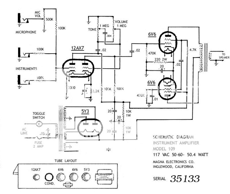
This self-split arrangement was used in the Magnatone 109 amplifier:
[IMG:800:673]http://i497.photobucket.com/albums/rr33 ... ne_109.jpg[/img]
The output valves can only be operated in Class A. If the first output valve in the signal chain is driven to cutoff, there is no drive signal for the second valve.
[IMG:800:673]http://i497.photobucket.com/albums/rr33 ... ne_109.jpg[/img]
The output valves can only be operated in Class A. If the first output valve in the signal chain is driven to cutoff, there is no drive signal for the second valve.