
I can't tell if you've got real Switchcraft or imitation. There is no consistency for lug orientation, so without a side view of the jack, it is impossible to know what lug is attached to what. With the imitations, you might even get inconsistency from on piece to another.
I meant to post a different picture yesterday. Here it is and it should help you check the jack wiring. Trace the lugs to the sleeve, the switch, and the tip so you are sure. Don't just go by the lug position.
Ground that volume pot first. It's possible the jack is fine.
My Very First Ever Build AA764 Vibro Champ. (Cab is here)
Moderators: pompeiisneaks, Colossal
Re: My Very First Ever Build AA764 Vibro Champ. (Cab is here)
You do not have the required permissions to view the files attached to this post.
Re: My Very First Ever Build AA764 Vibro Champ. (Cab is here)
Sorry I wasn't more specific about the jacks, follow Phil's instructions.
If you pick up any RF or other noise, you may want to locate the two 68K resistors right on pin 2 of V1.
You can hang them on pin 2 but using a small terminal strip attached nearby would be best.
If you pick up any RF or other noise, you may want to locate the two 68K resistors right on pin 2 of V1.
You can hang them on pin 2 but using a small terminal strip attached nearby would be best.
You do not have the required permissions to view the files attached to this post.
Tom
Don't let that smoke out!
Don't let that smoke out!
Re: My Very First Ever Build AA764 Vibro Champ. (Cab is here)
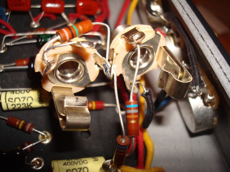
I rewired the switches. (Yes I'm using switchcraft) I think they should be ok but I'm still getting no sound.
What I do have is a wire running from the 2700 resistor to tip (Hot) on the speaker output. (I also have the OT 3.2 ohm wire running to the same spot.) Could that be an issue?
Here are some pics.
[IMG:800:600]http://i114.photobucket.com/albums/n271 ... C01982.jpg[/img]
[IMG:800:600]http://i114.photobucket.com/albums/n271 ... C01983.jpg[/img]
Re: My Very First Ever Build AA764 Vibro Champ. (Cab is here)
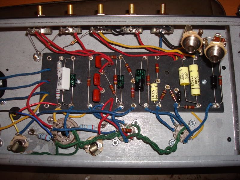
Crap, I just noticed I'm missing a bunch of grounds all over the place. Im missing the grounds on both 12AX7's and all the ones on the board on the side that faces the pots.... 

Re: My Very First Ever Build AA764 Vibro Champ. (Cab is here)
I thought you wired your filaments like I had said not the original way then there are no grounds on your 12ax7.
Mark
Mark
Re: My Very First Ever Build AA764 Vibro Champ. (Cab is here)
I did wire them that way but added a ground. I will remove the ground. When I plugged it in last I got a loud hum/buzz.M Fowler wrote:I thought you wired your filaments like I had said not the original way then there are no grounds on your 12ax7.
Mark
Re: My Very First Ever Build AA764 Vibro Champ. (Cab is here)
I can't tell from the photo but on the first two nine pin sockets, do you have the heaters wired so that pins 4 & 5 are joined together and the other wire goes to pin 9?
I believe you have your 100R resistors wired right.
That is, if each is soldered to the chassis.
I personally would have put a ground lug on a socket screw but whatever.
You are correct about the 2K7 resistor and the yellow wire going to the tip of the spkr jack.
Check all your under board wires as well, those are easy to miss.
Tom
Don't let that smoke out!
Don't let that smoke out!
Re: My Very First Ever Build AA764 Vibro Champ. (Cab is here)
Yes I do have them wired that way.Structo wrote:I can't tell from the photo but on the first two nine pin sockets, do you have the heaters wired so that pins 4 & 5 are joined together and the other wire goes to pin 9?
I just plugged it in again and got a loud hum. Nothing more. I'm going to double check every single connection against the layout again. I checked continuity at the "A" and "X" spot as well and it seems fine there.
Re: My Very First Ever Build AA764 Vibro Champ. (Cab is here)
On the volume control third pin to the left that should be grounded either to pot and you have a black wire going from that pin to your input jack?
Also I am concerned about point A to A wiring as well as X to X under the board.
Where is the grounding of V1 goes to the resistor/cap on far right side of board 25uf/25v & 1.5k then to ground is that grounded somewhere?
Also I am concerned about point A to A wiring as well as X to X under the board.
Where is the grounding of V1 goes to the resistor/cap on far right side of board 25uf/25v & 1.5k then to ground is that grounded somewhere?
Last edited by M Fowler on Wed May 13, 2009 3:36 am, edited 1 time in total.
Re: My Very First Ever Build AA764 Vibro Champ. (Cab is here)
The Volume pot I grounded to the ground on the input but I will move to the common ground point I got near the last pot. (Or is it ok to ground on the input?)M Fowler wrote:On the volume control three pin to the left that should be grounded either to pot and you have a black wire going from that pin to your input jack?
Also I am concerned about point A to A wiring as well as X to X under the board.
Where is the grounding of V1 goes to the resistor/cap on far right side of board 25uf/25v & 1.5k then to ground is that grounded somewhere?
Points A to A and X to X should be good and they do check for continuity.
The 25 Uf/25v cap is grounded to the common ground over by the far left pot.
Re: My Very First Ever Build AA764 Vibro Champ. (Cab is here)
I suggest first step back and give this a short rest to clear your mind. Then, get a fresh copy of the layout AND the schematic. Check the job twice, once to the layout and then to the schematic. Start at one end and work towards the other. Use a highlighter to indicate what you've verified.
This will be a tedious, but instructive experience. What you learn from it will stick with you for your next build. There is no substitute for sweat equity. This is an amp with only a few parts, so it won't be awful to do. There is also a very good chance you will find the problem(s).
Once you've verified the build as correct, power up and take voltage reading for the tube pins. Post the results. Omit posting the heater voltage, as that is clutter, but do check for 6.3vac there.
You've got to work thorough this methodically, not scattershot. It's the right way to fix it. You have a tidy build and you are almost there. Keep going. Keep us posted.
Re: My Very First Ever Build AA764 Vibro Champ. (Cab is here)
Will do sir. Thx for your input.Phil_S wrote:I suggest first step back and give this a short rest to clear your mind. Then, get a fresh copy of the layout AND the schematic. Check the job twice, once to the layout and then to the schematic. Start at one end and work towards the other. Use a highlighter to indicate what you've verified.
This will be a tedious, but instructive experience. What you learn from it will stick with you for your next build. There is no substitute for sweat equity. This is an amp with only a few parts, so it won't be awful to do. There is also a very good chance you will find the problem(s).
Once you've verified the build as correct, power up and take voltage reading for the tube pins. Post the results. Omit posting the heater voltage, as that is clutter, but do check for 6.3vac there.
You've got to work thorough this methodically, not scattershot. It's the right way to fix it. You have a tidy build and you are almost there. Keep going. Keep us posted.
Re: My Very First Ever Build AA764 Vibro Champ. (Cab is here)
I'm not sure if you were talking to me "sir" or not. <attempt at humor>
Here are a few things to look out for:
-Are all of the grounds made? I don't see them, but I'm not there.
-In particular, is the output transformer grounded (black wire)?
-I don't see the A to A connection from the corner of the board to the place where the two 100K resistors make a V shape.
-Did you complete the wire from the outer leg of the intensity pot to the cathode on V1. This is made where the cathode resistor/cap are on the board, on the "tube side". This would be the 5th eyelet from the end (counting from V1 edge).
Re: My Very First Ever Build AA764 Vibro Champ. (Cab is here)
Lol @ the "sir"Phil_S wrote:I'm not sure if you were talking to me "sir" or not. <attempt at humor>
Here are a few things to look out for:
-Are all of the grounds made? I don't see them, but I'm not there.
-In particular, is the output transformer grounded (black wire)?
-I don't see the A to A connection from the corner of the board to the place where the two 100K resistors make a V shape.
-Did you complete the wire from the outer leg of the intensity pot to the cathode on V1. This is made where the cathode resistor/cap are on the board, on the "tube side". This would be the 5th eyelet from the end (counting from V1 edge).
Thank you Phil,
One ground is missing from the volume pot but I'm adding it now.
Ot is grounded.
The A to A connection and X to X should be fine as they both test for continuity.
The cathode to the leg connection on the intensity pot do check for continuity as well.
What I did find was one leg from the 10 uf cap had become undone. The soldering iron is warming up as we speak.
Re: My Very First Ever Build AA764 Vibro Champ. (Cab is here)
I do not see the 330pf cap from pin 2 to pin 5 on the 6V6, it is shown on the schematic and layout. I had to down load your picture so I could blow it up to see better. 
I am also concerned about under board wiring since we did not see any pictures of that. There is a lot going on in that layout most of which are just wires passing under the board but the other ones also indicated by dashes on the layout are connections.
Mark
I am also concerned about under board wiring since we did not see any pictures of that. There is a lot going on in that layout most of which are just wires passing under the board but the other ones also indicated by dashes on the layout are connections.
Mark