If you halve Ra and Rk to hold the same bias point, the gain of paralleled triodes will be the same as for a single triode.10thTx wrote:IF you find that you are NOT using both input jacks, then you could parallel V1 for 30% more gain and NO increase in floor noise.
Silvertone 1482 Build
Moderators: pompeiisneaks, Colossal
-
martin manning

- Posts: 14308
- Joined: Sun Jul 06, 2008 12:43 am
- Location: 39°06' N 84°30' W
Re: Silvertone 1482 Build
Re: Silvertone 1482 Build
My understanding is that he would need to half the plate resistor value and keep the cathode resistor value the same as in the schematic I posted earlier in the thread.
So if the original is 330k/plate & 2.2k/cathode, try 150k/2.2k paralleled.
Can you confirm that this is correct?
With respect, 10thtx
So if the original is 330k/plate & 2.2k/cathode, try 150k/2.2k paralleled.
Can you confirm that this is correct?
With respect, 10thtx
-
martin manning
- Posts: 14308
- Joined: Sun Jul 06, 2008 12:43 am
- Location: 39°06' N 84°30' W
Re: Silvertone 1482 Build
Which schematic and where are you adding the parallel connections?
Re: Silvertone 1482 Build
It's on the first page of this very thread. It is the 6th post on the thread.
The schematic is titled 1482 Silvertone Reverb.
It shows a paralleled V1 and a one tube reverb added.
There is both a GIF and SCH editable version posted on that post
10thtx
The schematic is titled 1482 Silvertone Reverb.
It shows a paralleled V1 and a one tube reverb added.
There is both a GIF and SCH editable version posted on that post
10thtx
-
martin manning
- Posts: 14308
- Joined: Sun Jul 06, 2008 12:43 am
- Location: 39°06' N 84°30' W
Re: Silvertone 1482 Build
Since the two triodes shared a cathode resistor originally, you do not have to reduce that by half, but the gain for paralleled triodes is the same as for each one individually, assuming you halve the plate load.
-
dawsonaudio
- Posts: 110
- Joined: Mon Jun 30, 2014 6:43 pm
Re: Silvertone 1482 Build
The only other thing that isn't working here is the tremolo. Should it engage with or without the pedal inserted? I soldered a bridge to close the circuit but still no tremolo.
Voltage at pin 2 of the 6au6 is 182vdc and pin 5 is 372vdc. That is quite high as far as the previous posted schematic with a voltage at pin 2 of 75vdc. Obviously it will be a little higher with my high b+, but the other test points were within range. I also swapped 6au6 tubes with no luck. Maybe the previous photos I posted show a mistake on the pot wiring.
Any suggestions? Thanks again for the help here.
Nate
-
dawsonaudio
- Posts: 110
- Joined: Mon Jun 30, 2014 6:43 pm
Re: Silvertone 1482 Build
Here is the diagram I followed and maybe the 6au6 is wired wrong or I'm looking at the original schematic and tube data wrong.
https://tubeamparchive.com/download/file.php?id=29340
Maybe pin 2 and 7 are supposed to be grounded instead of 6 and 7. Pin 6 should go to the 330k x2 and .5 cap. I have it currently wired with 6 and 7 to ground and 2 to the 330k and .5 cap.
Am I looking at it correctly? I got the tube data for the 6au6 off google as far as the pin out diagram.
Thanks.
-
dawsonaudio
- Posts: 110
- Joined: Mon Jun 30, 2014 6:43 pm
Re: Silvertone 1482 Build
I'm pretty sure that is the correct wiring. I checked on some images off the web. Pin 2 and 7 should connect together instead of 6 and 7. 6 will connect to the .5 and 330k/b+ instead of pin 2. Here is the image I zoomed in on off of this site. 6au6 socket is on the right toward the bottom, the left tube socket. The one next is the 6x4 rectifier socket.
[img 768]http://www.regiscoyne.com/silvertone148 ... 482_04.jpg[/img]
[img
 768]http://www.regiscoyne.com/silvertone148 ... 482_04.jpg[/img]
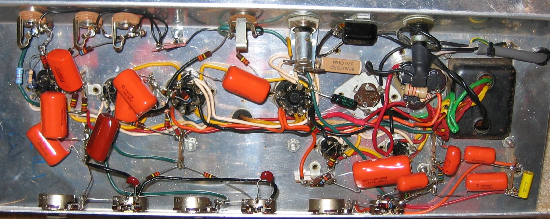
-
dawsonaudio
- Posts: 110
- Joined: Mon Jun 30, 2014 6:43 pm
Re: Silvertone 1482 Build
This is a schematic showing the 6au6 pins from a 1472 which probably is the same circuit:
http://www.freeinfosociety.com/electron ... ne1472.pdf
Should have quadruple checked everything first. Hope the rewire makes the difference......
Well, that still didn't fix the tremolo. There must be something else wired wrong. Any ideas from the original photos I posted? It's gotta be something simple I'm overlooking. Maybe both of the 6au6 tubes aren't working.
-
dawsonaudio
- Posts: 110
- Joined: Mon Jun 30, 2014 6:43 pm
Re: Silvertone 1482 Build
I found the problem with my tremolo circuit. The .05 cap was attached to the b+ at the 680pf/68k junction instead of to pin 5 of the 6au6. Another thing I should have checked on the schematic against the provided layout.
The tremolo now sounds great. I will draw up and post my modified layout with the changes.
Thanks again for the help here.
Nate
The tremolo now sounds great. I will draw up and post my modified layout with the changes.
Thanks again for the help here.
Nate
Re: Silvertone 1482 Build
This is an old thread, but who made the Output Transformer ?
I need one.
I need one.