
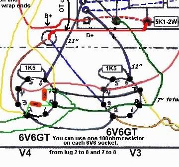
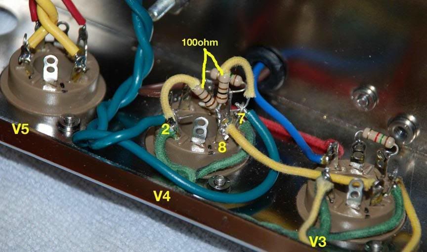
Concerning the detail of the two 100 ohm resistors. Are these two circuits equivalent. I have moved the resistors to the octal and removed the wires going to the 22uf. all the other wires are still in place.
[IMG:380:342]http://i260.photobucket.com/albums/ii9/ ... hmorig.jpg[/img]
[IMG:360:336]http://i260.photobucket.com/albums/ii9/ ... 0ohm-1.jpg[/img]
Deluxe circuit question
Moderators: pompeiisneaks, Colossal
-
collinsamps
- Posts: 223
- Joined: Fri Mar 06, 2009 1:51 pm
- Location: North Carolina
- Contact:
Picture
Ok, I was simply trying to see if I had the change correct as i was following the pics that I received with the kit I have. I have it as shown in the pic for now. i guess i can swap it out later if it is noisy. So the way I have the circuit re-drawn is ok and not gonna do any damage?
thanks for your help.
best ange
[IMG:864:510]http://i260.photobucket.com/albums/ii9/ ... ockets.jpg[/img]
thanks for your help.
best ange
[IMG:864:510]http://i260.photobucket.com/albums/ii9/ ... ockets.jpg[/img]
-
collinsamps
- Posts: 223
- Joined: Fri Mar 06, 2009 1:51 pm
- Location: North Carolina
- Contact:
Re: Deluxe circuit question
No you're fine that way as long as you continue the pin 8 connection which isn't hooked up in the pic.. I'm not sure what "Deluxe" you are building or where you got the kit from, but the original Fender likely had the 100 ohms resistors(on non 6.3-0-6.3 CT transformers only) mounted on the jewel lamp receptacle and grounded directly to the chassis. As long as they are in the 6.3V loop somewhere you're ok. I would recommend keeping lead length as short as possible, and if you are going direct to ground and not floating them above ground (a few diagrams on the web and here somewhere) on the PS rail or above a cathode resistor, you may consider grounding pin 8 to the chassis by the sockets if it's fixed biased.
-
azatplayer
- Posts: 556
- Joined: Thu Feb 26, 2009 7:59 pm
- Location: Great Southland
Re: Deluxe circuit question
Gotta build one of these soon.