Here´s my schem:
[IMG
 644]http://i68.photobucket.com/albums/i5/Mo ... rev-10.jpg[/img]
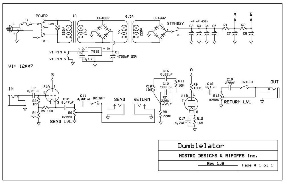
Questions:
1) I´m gonna power the tube heaters with 12V DC.It should actually be 12.6V, but with a 7812 regulator I´ll get 12V. Is that OK, or will it be bad for the tube?
2) Regarding supply voltages: Using xformers back to back like shown, I calculated that I´ll get, at the 2nd xformer primary (220V side) around 293V. After the rectifier bridge, I should get 293 x 1,414= 414,69V DC minus the diodes drop (all this is theory, haven´t tried it yet). Now, the part of the schem from the standby switch to the A and B points I´m not that sure... The point A is supposed to get 368V, and the point B 256V. I´m not that sure of how to get those values... I guess R1 and R2 could be 22K, and C7 / C8 could be 22uF? Also, are C2/3/4/5 too much filtering? could I do with just two 47 uF caps? That part of the schem is a gray area to me...
3) About the fuse F1, I´m not that sure of the value. Would 1A slo blo be OK? Or less?
4) anything else you see that wouldn´t work?
Thanks for reading! Any help will be useful.