Tube Rectifier resistor/choke question
Moderators: pompeiisneaks, Colossal
Tube Rectifier resistor/choke question
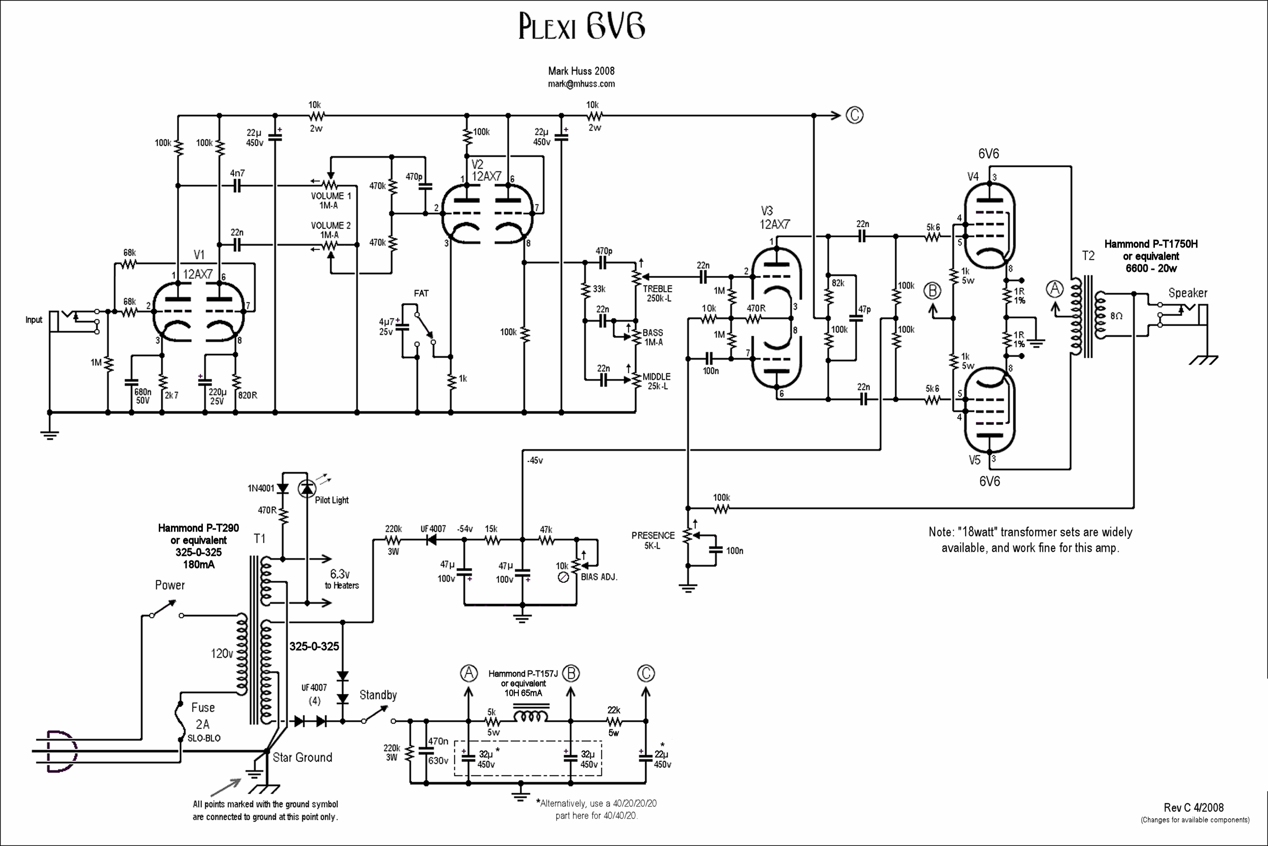
I built the Huss Plexi 6V6 but instead used a tube rectifier instead of the ss rectification on his schematic. On the original schem there is a 5K/5W resistor after the diodes and before the choke. Is this a sag resistor and is it needed when using a tube rectifier?
Owner/luthier of Flintrock Guitar Shop, Flint, MI.
Owner of Hawkins Effects Pedals
Owner of Hawkins Effects Pedals
-
gingertube
- Posts: 531
- Joined: Mon Nov 14, 2011 2:29 am
- Location: Adelaide, South Oz
Re: Tube Rectifier resistor/choke question
The 5K in series with the choke is after the "heavy current" feed to the output tubes via the Output Transformer Centre Tap. It is relevant ONLY to the Output Tube Screen Supply (labelled "B"") and Phase Splitter and Preamp Supply (labelled"C").
http://www.mhuss.com/Plexi6V6/Plexi6V6c.gif
It is not a "SAG" resistor. Its primary purpose (my guess) is to make sure that the output tube screen supply is at little lower voltage than the anodes when at idle. The choke is big enough that you would get adequate filtering to the screen without the resistor so it can only have been included to drop the voltage a little.
It seems that this is the way to get the best tone. The EL84 guys on the various amp forums are very loud in saying that a voltage drop mod like this (to get the screens a few volts below the anodes) is required to get the best tone. 6V6 and EL84 are very different beasts but I would not be surprised to find out that what works for EL84 will also work for 6V6.
Cheers,
Ian

Re: Tube Rectifier resistor/choke question
To add to Ian's discussion, which is spot on, Mark built the first 6V6 Plexi as a parts-on-hand build. So whatever he had on hand when creativity struck is what he used. This included a very hot PT, a Vibrolux running at 345-0-345. This produced rectified voltages of about 440+VDC. Way hot for all but JJ 6V6Ss which are more like small bottle 6L6s, but I digress. The added 5k in series with the choke is to reduce the screen voltages down to prevent over dissipation with those high plate voltages. Those amps run loud and proud and the added compression sounds killer. I checked my build notes and my plate voltages were 447VDC and screens at 412VDC with a 5k 5W resistor in series with a 10H 280R choke. I used a Mercury Vibrolux PT and a 7k8 Marshall 20W OT. For fun I added a switchable tube/SS rectifier. I preferred solid state mode and 47-5k/choke-47-22-22-22 filtration. Smokin' amp.
Re: Tube Rectifier resistor/choke question
I envisage a lot of sag in the screen supply, ie the screen node voltage at high signal levels will be significantly lower than the static level.
Which, as noted, is likely to result in a strong compression effect at such levels.
Pete
Which, as noted, is likely to result in a strong compression effect at such levels.
Pete
https://www.justgiving.com/page/5-in-5-for-charlie This is my step son and his family. He is running 5 marathons in 5 days to support the research into STXBP1, the genetic condition my grandson Charlie has. Please consider supporting him!
Re: Tube Rectifier resistor/choke question
I'm using an old PT from a tube radio, so my voltages are a bit different and not as hot. I'm still getting this fuzzy ugly distortion at anything over 2 on the volume. Here's some up to date voltages I took this morning with no power tubes installed:
Pin 8 rectifier tube 5U4 - 410V
After 5k/5W pre-choke resistor - 390V
Voltage at "B" - 380V
Voltage at "C" - 253V
6V6 pin 3 - 410V
6V6 pin 4 - 373V
6V6 pin 5 - -24
P.I. pin 1 & 6 - 145V
Anything look off?
Pin 8 rectifier tube 5U4 - 410V
After 5k/5W pre-choke resistor - 390V
Voltage at "B" - 380V
Voltage at "C" - 253V
6V6 pin 3 - 410V
6V6 pin 4 - 373V
6V6 pin 5 - -24
P.I. pin 1 & 6 - 145V
Anything look off?
Owner/luthier of Flintrock Guitar Shop, Flint, MI.
Owner of Hawkins Effects Pedals
Owner of Hawkins Effects Pedals
Re: Tube Rectifier resistor/choke question
Fuzzy ugly distortion suggests a lead dress problem, oscillation, component crosstalk, or other issue. There isn't a lot of headroom in the amp so distortion comes on pretty early but it should not be fuzzy/ugly. The region around the 470k + 470k/470p mixing resistors can be microphonic and sensitive so watch your lead dress there. I would go through and document the voltages on each pin of each tube, as you have with the power tubes and PI and see if the preamp voltages are reasonable.
Have you measured power tube current using 1R 1% current resistors? Your bias voltage seems high at -24V.
Have you measured power tube current using 1R 1% current resistors? Your bias voltage seems high at -24V.
Re: Tube Rectifier resistor/choke question
I did and was at 76% dissipation. That was with some low testing JJ's. I just got some Sylvanias that I'll put in and recheck the bias as well as post some pin by pin voltages.
Owner/luthier of Flintrock Guitar Shop, Flint, MI.
Owner of Hawkins Effects Pedals
Owner of Hawkins Effects Pedals
Re: Tube Rectifier resistor/choke question
Some current numbers I just pulled:
A - 347V
B - 310V
c - 214V
V1
-------
pin1 127v
pin6 98v
pin8 93v
V2
--------
pin1 142v
pin6 185v
pin7 146v
pin8 145v
V3 P.I.
---------
pin1 141v
pin2 9v
pin3 24v
pin6 135v
pin7 8v
pin8 24v
6V6
---------
pin3 346v
pin4 305v
pin5 -24v
Current across 1 ohm resistors pin8 23.8mv, 20.6mv
A - 347V
B - 310V
c - 214V
V1
-------
pin1 127v
pin6 98v
pin8 93v
V2
--------
pin1 142v
pin6 185v
pin7 146v
pin8 145v
V3 P.I.
---------
pin1 141v
pin2 9v
pin3 24v
pin6 135v
pin7 8v
pin8 24v
6V6
---------
pin3 346v
pin4 305v
pin5 -24v
Current across 1 ohm resistors pin8 23.8mv, 20.6mv
Owner/luthier of Flintrock Guitar Shop, Flint, MI.
Owner of Hawkins Effects Pedals
Owner of Hawkins Effects Pedals
Re: Tube Rectifier resistor/choke question
You're a little on the low side with V1 pins 1 and 6. Did you mean 0.93V on pin 8? If you didn't, there's something wrong there.flintrock wrote:V1
-------
pin1 127v
pin6 98v
pin8 93v
Your PI (V3) grid voltages (pins 2 and 7) look odd. Based on a sample I have of mine and 3 other builders' voltages, grid voltages should be 24-38V.
Your power tube currents seem reasonable for the plate voltage.
Re: Tube Rectifier resistor/choke question
Oops yes no voltage on pin 8 of v1. I have been through that phase inverter circuit over and again and I see nothing wrong with it. I swapped in a brand new tube and checked again, same voltages.
Owner/luthier of Flintrock Guitar Shop, Flint, MI.
Owner of Hawkins Effects Pedals
Owner of Hawkins Effects Pedals
Re: Tube Rectifier resistor/choke question
Went through with an audio probe and everything sounds fine until the output of the phase inverter pins 1& 6, sound isnt quite as clear.
Owner/luthier of Flintrock Guitar Shop, Flint, MI.
Owner of Hawkins Effects Pedals
Owner of Hawkins Effects Pedals
Re: Tube Rectifier resistor/choke question
Colossal wrote:
Your PI (V3) grid voltages (pins 2 and 7) look odd. Based on a sample I have of mine and 3 other builders' voltages, grid voltages should be 24-38V.
The PI grid voltages will change when measured because of how high the impedance is at that point unless the meter has an extremely high impedance. Measure at the junction of the cathode and tail resistors for the grid voltage on an LTPPI.flintrock wrote: I have been through that phase inverter circuit over and again and I see nothing wrong with it. I swapped in a brand new tube and checked again, same voltages.
Matt
Re: Tube Rectifier resistor/choke question
I have 24v at that junction. I changed out the 100k resistor across v2 with a new one as it was really close to the heater wires. Signal cleaned up after v2 where it was fuzzy before. The sound has improved but still not exactly right.
Owner/luthier of Flintrock Guitar Shop, Flint, MI.
Owner of Hawkins Effects Pedals
Owner of Hawkins Effects Pedals
Re: Tube Rectifier resistor/choke question
Good!flintrock wrote:I have 24v at that junction.
Matt's 6V6 Plexi voltages is one of the ones I was referencing.
Re: Tube Rectifier resistor/choke question
I will say it sounds good up to about halfway, then just gets really compressed.
Owner/luthier of Flintrock Guitar Shop, Flint, MI.
Owner of Hawkins Effects Pedals
Owner of Hawkins Effects Pedals