interesting phase inverter

General discussion area for tube amps.

Moderators: pompeiisneaks, Colossal

pula58
Posts: 414
Joined: Tue Jan 26, 2010 4:30 am

Re: interesting phase inverter

Post by pula58 »

darryl_h wrote:This self-split arrangement was used in the Magnatone 109 amplifier:

[IMG:800:673]http://i497.photobucket.com/albums/rr33 ... ne_109.jpg[/img]

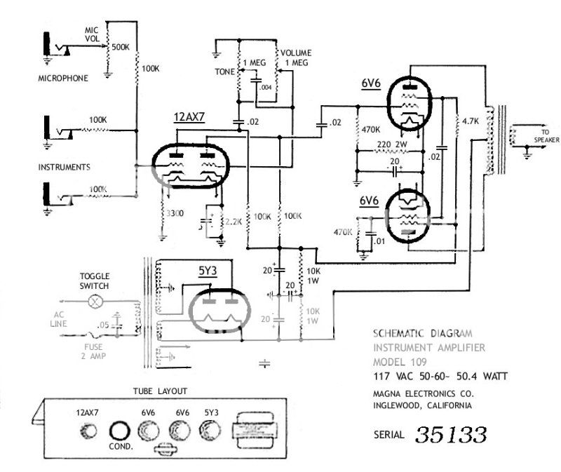
The output valves can only be operated in Class A. If the first output valve in the signal chain is driven to cutoff, there is no drive signal for the second valve.
Wow, that is nearly identical to the circuit I am working-on! I can see now that my thinking was correct: the screen of the 2nd output tube (who's grid is driven by the screen of the 1st output tube) should be connected directly to the screen supply. ONLY the 1st tubes screen gets the 4.7K placed between its screen and the screen supply.

I am going down to the lab now to see....
User avatar
Structo
Posts: 15446
Joined: Wed Oct 17, 2007 1:01 am
Location: Oregon

Re: interesting phase inverter

Post by Structo »

I'm not sure I understand how you explained it but the screen resistor resides between the two power tube screens, then connects to the power supply.

(backs away slowly.....)
Tom

Don't let that smoke out!
Andy Le Blanc
Posts: 2582
Joined: Sat Dec 22, 2007 1:16 am
Location: central Maine

Re: interesting phase inverter

Post by Andy Le Blanc »

heres another self-split....

extra simple, the variation is from where of how the inverting grid is sourced.
looks like a 12au7 moon light or a lunchbox scaled up, but its the other way round, I've built this one on 50w iron and kt88, ripping harp rig..

the previous look a bit like an ultra path, its what you use as feedback to linearize and extend bandwidth
lazymaryamps
Post Reply