
That's a sticker actually... I designed it and my friend printed it for me. He has a plotter, so size is not an issue.Structo wrote:Thanks for the kind words guys.
Hey, how did you do the front panel graphics?
That looks killer!
My Dumbleator
Moderators: pompeiisneaks, Colossal
Re: My Dumbleator
Re: My Dumbleator
That's exactly what I did... my voltages looks much better now.honeydip wrote:I'm glad you found it
If you don't have 820R just take something close to that like 500R-1K5 with the appropriate power handling capability, it'll work even if the voltage won't be exactly what you were shooting for.
Now, tell us if it works and how it sounds, soundfiles appriciated.
BTW, I'm living in germany and orderer my DALE resistors and lots of other stuff over MOUSER.com and believe it or not, they send everything over to europe in 3 days with free shipment if your order is above 75Euros. It's easy.
Same thing with tubeandmore.com but longer delivery.
Best regards.
Jan
311V and 255V
Thanks for the tip... next time I'm going with mouser.com
Thanks again
You do not have the required permissions to view the files attached to this post.
Re: My Dumbleator
I had some difficulty trying to get the voltages where they should be.
I'm using a 12ax7, with the 1K8/ 27K resistors on the cathode follower stage.
This PT is the Fender Stand Alone Reverb replacement PT.
At first I had a 10K on the first node and a 100K on the second.
Voltages were way low.
So I started tacking in different combinations.
I came up with 680R on the first node and 50K on the second.
(is that a bad thing to have those weird different values there?)
What do you guys that are using that PT using for dropping resistors?
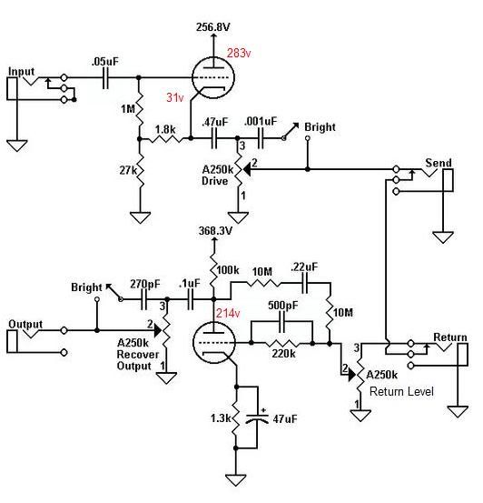
The rectified (bridge) voltage is 340v.
On pin 1 plate,283v
On pin 6 plate,214v
And on pin 3 cathode, 31v
I also notice the voltages can fluctuate a few volts either way depending on the tube. (12ax7)
I haven't played through it yet. Need to modify the amp.
[IMG:522:507]http://i23.photobucket.com/albums/b392/ ... String.jpg[/img]
[IMG:532:553]http://i23.photobucket.com/albums/b392/ ... 122309.jpg[/img]
I'm using a 12ax7, with the 1K8/ 27K resistors on the cathode follower stage.
This PT is the Fender Stand Alone Reverb replacement PT.
At first I had a 10K on the first node and a 100K on the second.
Voltages were way low.
So I started tacking in different combinations.
I came up with 680R on the first node and 50K on the second.
(is that a bad thing to have those weird different values there?)
What do you guys that are using that PT using for dropping resistors?
The rectified (bridge) voltage is 340v.
On pin 1 plate,283v
On pin 6 plate,214v
And on pin 3 cathode, 31v
I also notice the voltages can fluctuate a few volts either way depending on the tube. (12ax7)
I haven't played through it yet. Need to modify the amp.
[IMG:522:507]http://i23.photobucket.com/albums/b392/ ... String.jpg[/img]
[IMG:532:553]http://i23.photobucket.com/albums/b392/ ... 122309.jpg[/img]
Tom
Don't let that smoke out!
Don't let that smoke out!
-
martin manning

- Posts: 14308
- Joined: Sun Jul 06, 2008 12:43 am
- Location: 39°06' N 84°30' W
Re: My Dumbleator
Tom, I think you are about as close as you are going to get on the node 1 voltage at 337. You can't really do much better because the voltage out of your C-L-C filter is what, 338.5? ...and, the operating point is probably pretty well centered right where it is given the B+ you have.
The only problem with lowering the value of the first dropping resistor is that the knee of the LP filter formed with the first 30uF moves up in frequency. However, you've probably got pretty low ripple going in because of the choke, and at 120Hz the 680R/30uF is knocking that down by another 24dB.
You could change the 50K to a 68K and take another 20V or so off the CF plate if you want to get closer to the voltages on the schematic, but I'm betting it will work fine as-is. 30V is in the right ballpark for the cathode voltage.
Someone who knows more about the nuances of these things might have more to add...
MPM
Re: My Dumbleator
Thanks Martin.
From what I have read here, I thought the cathode follower plate is supposed to be around 255v for the best operation?
And the cathode itself to be at 30v.
I've tried to run these numbers through the Duncan PS designer but the numbers don't come out to what I am experiencing.
I've looked around for more info for calculating dropping resistors and the Time Constant but didn't have real good luck.
I believe Scott said this to another member:
Raise the dropping resistor feeding the follower. Shoot for 260V on pin 1. Anything 25V or higher on pin 3 is plenty. Real deals have 250V or so on the follower. Stock drop is 100K. Try increasing the drop to at least 75K or so.
And there was this:
You want to see 257 vDC on the plate of the cathode follower side, and you want to see 368 vDC before the 100K plate load resistor, and 229 vDC on the plate itself. the real article uses a 100K dropping resistor between 2 33uf filters
Tom
Don't let that smoke out!
Don't let that smoke out!
-
martin manning
- Posts: 14308
- Joined: Sun Jul 06, 2008 12:43 am
- Location: 39°06' N 84°30' W
Re: My Dumbleator
Keep in mind that you are a good 40V low coming out of your rectifier as compared to the voltage doubler schematic that has been shown. That's why your first dropping resistor has to be so much smaller, and you are still missing the B+ for the recover stage by 31V (337 vs. 368). It's plate will also be low by about the same amount. That's 31V you don't have to lose with the second dropping resistor, so you'll only need 68 or 75K instead of 100K like in the schematic. If there is something magic about 260V on the CF plate, then you can adjust your 50K up until you get that.
I put your numbers into the PSU designer today and got very good agreement using current sinks to represent the triodes. I also checked the load lines on nominal 12AX7 plate curves, and they look good. As you saw, different tubes will draw slightly different current and nudge the voltages around some, so you may want to do some tweaking.
MPM
Re: My Dumbleator
Thanks a lot for that Martin.
I probably don't know how to set up the PS designer.
I tried to make it look just like how I have mine but didn't get the voltage results I expected.
For what it's worth and I mean no offense to the guy that designed it but the PCB file for the Dumbleator seems wrong to me.
The .05uf cap should go to Pin 2 the grid not to the cathode.
I think the 1K8 and 1M resistor should be switched in this layout.
The .05 and .47 are backwards as well, unless I am completely off the mark.
At least according to the schematic. I hope that is accurate and in comparing Brandon's build to the schematic they match.
Just thought I would throw that out there in case somebody makes some PCB's.
The traces look correct, it's just the layout is wrong.
https://tubeamparchive.com/download/file.php?id=8408
Tom
Don't let that smoke out!
Don't let that smoke out!
-
martin manning
- Posts: 14308
- Joined: Sun Jul 06, 2008 12:43 am
- Location: 39°06' N 84°30' W
Re: My Dumbleator
No problem; I'm planning on building a D'lator so some of this work was already done.
On the linked PCB, looks like it's just the layout, with the 1K8 and 1M, and the 0.05 and the 0.47uF swapped as you said. If you do that, then the 0.05 goes to pin 2 as it should. Good catch. Maybe a post should be added to that thread?
MPM
On the linked PCB, looks like it's just the layout, with the 1K8 and 1M, and the 0.05 and the 0.47uF swapped as you said. If you do that, then the 0.05 goes to pin 2 as it should. Good catch. Maybe a post should be added to that thread?
MPM
Re: My Dumbleator
Tom, you mentioned maybe using waterslide decals and burying them in lacquer. I'm wondering if you know how to print white? I've been searching and haven't had any luck finding a solution.
Re: My Dumbleator
Hi Chip,
The only way I know is to use white background waterslide paper then what you do is use a black background or whatever color you want then the lettering is left clear so the white part of the waterslide becomes the lettering.
There is inkjet paper and laser paper.
With the inkjet paper, you have to topcoat the decal with a clear lacquer to make the ink water proof.
I believe the laser ink is water proof but I haven't used any because I don't have access to a laser printer.
I suppose a copy store would print it out for you for not much money.
Testers sells a small pack of waterslide paper that is half clear and half white background.
It's three 5 x 8" of clear and white each.
About $10 at a hobby store.
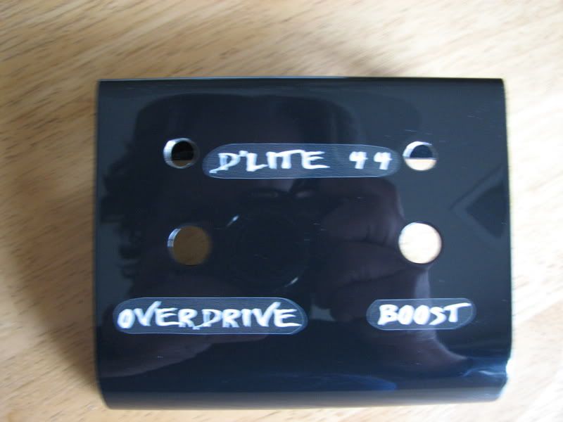
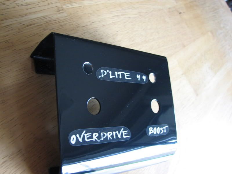
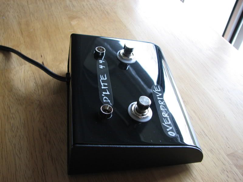
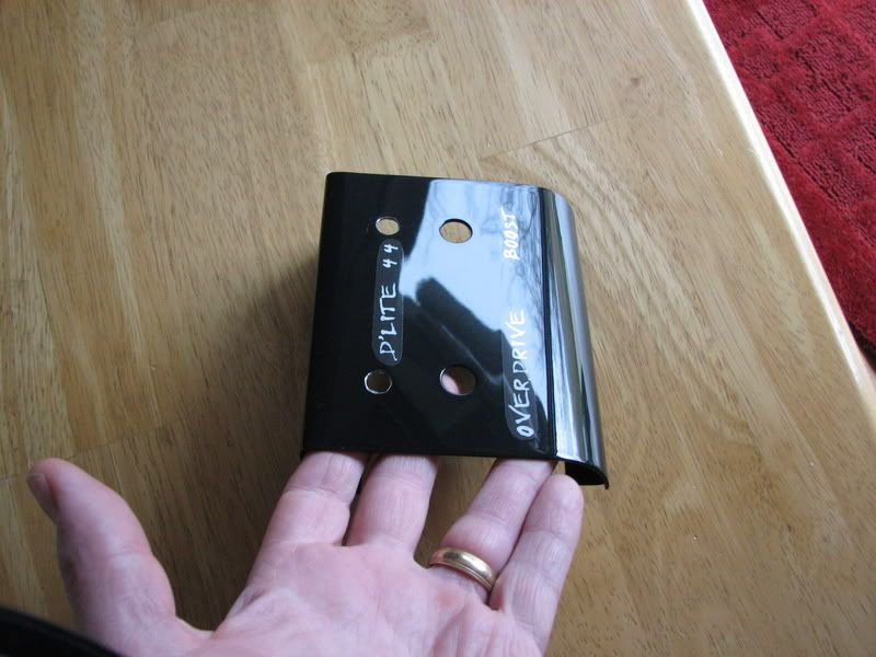
Here is a amp footswitch I did using the white paper.
The problem is, using an inkjet printer, the black isn't real deep black and the printer seems to have a hard time making the black real even.
I used Deft clear gloss lacquer on it.
You can see the black of the decal is not as black as the background.
And when you cut out the decals it leaves a sort of white line around it.
I really want to try some of the dry transfer lettering made by Datamark.
Then to make them durable I again would apply lacquer over it.
The only thing I don't know is how to get the lettering straight so it is aligned.
[IMG:800:600]http://i23.photobucket.com/albums/b392/ ... G_0283.jpg[/img]
[IMG:800:600]http://i23.photobucket.com/albums/b392/ ... G_0281.jpg[/img]
[IMG:800:600]http://i23.photobucket.com/albums/b392/ ... G_0287.jpg[/img]
[IMG:800:600]http://i23.photobucket.com/albums/b392/ ... G_0284.jpg[/img]
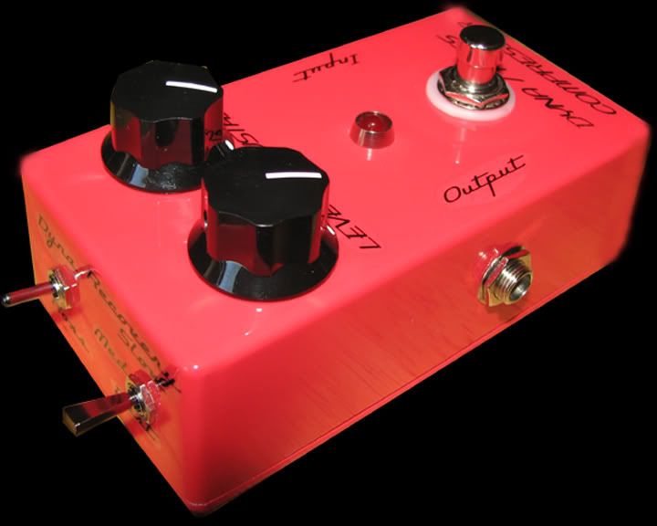
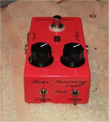
Here is a pedal I built that is a Dyna Comp and a Ross Compressor both in the same pedal.
I has a switch to go between the two since there is only minor differences between them.
These decals were printed on the clear decal paper and then again buried with Deft clear.
[IMG:720:576]http://i23.photobucket.com/albums/b392/ ... nished.jpg[/img]
[IMG:363:407]http://i23.photobucket.com/albums/b392/ ... G_0248.jpg[/img]
The only way I know is to use white background waterslide paper then what you do is use a black background or whatever color you want then the lettering is left clear so the white part of the waterslide becomes the lettering.
There is inkjet paper and laser paper.
With the inkjet paper, you have to topcoat the decal with a clear lacquer to make the ink water proof.
I believe the laser ink is water proof but I haven't used any because I don't have access to a laser printer.
I suppose a copy store would print it out for you for not much money.
Testers sells a small pack of waterslide paper that is half clear and half white background.
It's three 5 x 8" of clear and white each.
About $10 at a hobby store.
Here is a amp footswitch I did using the white paper.
The problem is, using an inkjet printer, the black isn't real deep black and the printer seems to have a hard time making the black real even.
I used Deft clear gloss lacquer on it.
You can see the black of the decal is not as black as the background.
And when you cut out the decals it leaves a sort of white line around it.
I really want to try some of the dry transfer lettering made by Datamark.
Then to make them durable I again would apply lacquer over it.
The only thing I don't know is how to get the lettering straight so it is aligned.
[IMG:800:600]http://i23.photobucket.com/albums/b392/ ... G_0283.jpg[/img]
[IMG:800:600]http://i23.photobucket.com/albums/b392/ ... G_0281.jpg[/img]
[IMG:800:600]http://i23.photobucket.com/albums/b392/ ... G_0287.jpg[/img]
[IMG:800:600]http://i23.photobucket.com/albums/b392/ ... G_0284.jpg[/img]
Here is a pedal I built that is a Dyna Comp and a Ross Compressor both in the same pedal.
I has a switch to go between the two since there is only minor differences between them.
These decals were printed on the clear decal paper and then again buried with Deft clear.
[IMG:720:576]http://i23.photobucket.com/albums/b392/ ... nished.jpg[/img]
[IMG:363:407]http://i23.photobucket.com/albums/b392/ ... G_0248.jpg[/img]
Tom
Don't let that smoke out!
Don't let that smoke out!
Re: My Dumbleator
BTW, this is the thread that has the D'Lator PCB layouts.
https://tubeamparchive.com/viewtopic.php?t=8406
Not sure if anybody wants to edit the file, I don't have the software to edit the pdf.
I suppose I could make a jpg and do it.
I just want everybody to be on the look out because I used this initially to design my eyelet board for the layout of components.
Now my pristine board is a bit hacked up.
I wish Tony had done the D'Lator layout before I attempted this.
I can read schematics but sometimes my head hurts when I have to think abstractly to design the layout of components.
Tom
Don't let that smoke out!
Don't let that smoke out!
Re: My Dumbleator
Thanks Tom. Happy New Year!
Re: My Dumbleator
Same to you Chip.
OK I changed the values on the PCB but of course this JPG probably won't be to scale.
EDITED to fix the .47uf cap value.
OK I changed the values on the PCB but of course this JPG probably won't be to scale.
EDITED to fix the .47uf cap value.
You do not have the required permissions to view the files attached to this post.
Last edited by Structo on Fri Jan 01, 2010 5:56 pm, edited 1 time in total.
Tom
Don't let that smoke out!
Don't let that smoke out!

Values
Tom, these are the posted values from Funk's tutorial. There is a discrepancy with your values. Is that due to the differing tranny.
ange
https://tubeamparchive.com/download/file.php?id=4673
ange
https://tubeamparchive.com/download/file.php?id=4673
Re: My Dumbleator
Tom,
You might want to go to the link below and download the free software called Front Panel Designer. It not real fancy but you can make some decent looking face plates with it. I printed mine on poster board in my printer. You could also convert it to a PDF file and go to Kinko's and get a different material printed.
http://www.frontpanelexpress.com/
Ken