Hi all,
New member here! First, I'd like to introduce myself...I'm still somewhat a newbie when it comes to tube amps, but I've built a couple of kits (both Ceriatone) and a couple of VJr conversions (one SE EL34 and one Baby Will). I'm a complete newbie to the Express from a build standpoint--but I've always LOVED the tone.
After spending a couple of weeks reading all I could on here about a scratch build, I decided to try a PCB build first. Given all there is to learn about these amps, I like the idea of starting slowly and learning as I go.
I've been blown away by the awesome support from this group of builders! It's the cool way you all support each other which makes me think I can pull this off. LOL, it's pretty different than over on TGP!
I've read the PCB thread and downloaded all the reference photos I could. RJ is going to help me with a chassis, and rock_mumbles was nice enough to supply me with a PCB.
I also lucked into a nice guy here in Minnesota who was getting out of building tube amps and I was able to score a MASSIVE amount of gear/parts/components--including a complete amp and two partial amps, one of which was an Express clone.
So I've got the Toneslut trannies and carefully went through the BOM and placed my Mouser/AES order. That's all arrived, so I've set about dry-fitting the PCB.
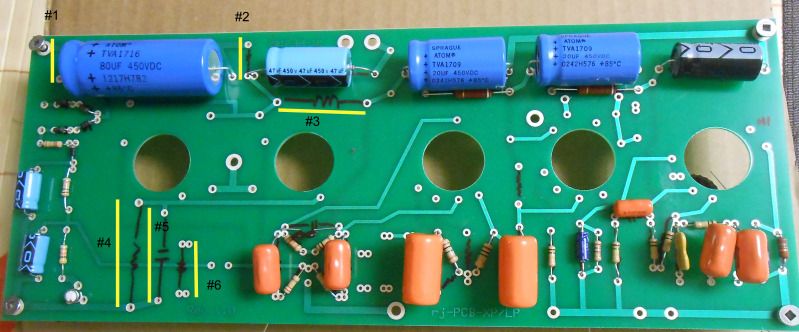
I've run into a couple of immediate questions--some of the components aren't super clear to me, so I've taken a picture of my dry-fit and photoshopped yellow lines and numbers representing the component values I'm unsure of. Could anyone take a quick look and let me know what they should be? Please note the numbers don't represent the schematic or BOM, just for my use.
As a small give-back, I'm planning on putting together a layout for the PCB version I have, "1.0"...hopefully this will help another new guy getting started.
Here's the picture:
[IMG:799:332]http://img.photobucket.com/albums/v519/ ... whole1.jpg[/img]
Thanks in advance! I should also apologize in advance for the million questions I'm likely to have...but I'm hoping to be able to pay it forward once I've learned more.
New PCB Express build - seeking advice
Moderators: pompeiisneaks, Colossal
-
rock_mumbles
- Posts: 244
- Joined: Mon Nov 17, 2008 2:03 am
- Location: Podunk, Idaho
- Contact:
Re: New PCB Express build - seeking advice
#1 and #2 are the bleed resistors for the HV supply 220k 3 watt ... the pcb has two bleed resistors, one on each side of the standby switch, the Express schematic has one (R23 & R24, the two 100 ohm 3W resistors in parallel)
#3 is the 18k dropping resistor (R26a & R26b shown as two 9.1k resistors)
#4 and #5 are the cathode resistor and cap for the 'Lerpoole' they are not used in the Express
#6 is the NFB resistor
#3 is the 18k dropping resistor (R26a & R26b shown as two 9.1k resistors)
#4 and #5 are the cathode resistor and cap for the 'Lerpoole' they are not used in the Express
#6 is the NFB resistor
Last edited by rock_mumbles on Fri Aug 10, 2012 5:11 am, edited 1 time in total.

Re: New PCB Express build - seeking advice
That is rj's latest version and I never did get a layout from rj on this board.
That is the bias area #4 & #5.
That is the bias area #4 & #5.
-
rock_mumbles
- Posts: 244
- Joined: Mon Nov 17, 2008 2:03 am
- Location: Podunk, Idaho
- Contact:
Re: New PCB Express build - seeking advice
You'll have to ground (jumper) either #4 or 5 (the cathodes) ... I'll look at my scans and look at the bias supply ...
There is a jumper from the output grid reference resistors on the 'lerpoole' (R17 & R18) to the ground BUS DO NOT install the jumper there, instead install the jumper just to the right of #6 in your picture, that will connect the grid reference resistors (R16 & R17) to the bias supply.
As a reference I labeled the components for the 'lerpoole' on rj's build picture.
Re: New PCB Express build - seeking advice
Thanks for all the help! I will order up two 220k 3 watt resistors. I also failed to notice the 1 watt designation for the 470 and 10k resistors on the PI/Presence circuit and ended up with 1/2 watt versions of each, so I need to order the correct ones as well.
Question: I have the pair of 9.1k 3 watt resistors called for in the BOM--could I run them in series to get the required 18K for the dropping resistor? Or am I better off just ordering the right one?
Question: I have the pair of 9.1k 3 watt resistors called for in the BOM--could I run them in series to get the required 18K for the dropping resistor? Or am I better off just ordering the right one?
-
rock_mumbles
- Posts: 244
- Joined: Mon Nov 17, 2008 2:03 am
- Location: Podunk, Idaho
- Contact:
Re: New PCB Express build - seeking advice
You use two 9.1k resistors for the 18k dropper ...
For the bleeder resistors I'd make sure to get resistors rated to 750V
For the bleeder resistors I'd make sure to get resistors rated to 750V

Re: New PCB Express build - seeking advice
This thread is timely for me. I have a complete Express PCB kit enroute from rj. The numbered layout is super helpful, thanks rock_mumbles.
-
rock_mumbles
- Posts: 244
- Joined: Mon Nov 17, 2008 2:03 am
- Location: Podunk, Idaho
- Contact:
Re: New PCB Express build - seeking advice
The numbered layout is for the two EL84 'Lerpoole' using the numbers from the Liverpool schematic posted in the Trainwreck Files .
We should get mattvon to do the same thing with his Exp build ... (hint - hint --- matt you there? take some nice hi-res pics of the populated board and ...)
We should get mattvon to do the same thing with his Exp build ... (hint - hint --- matt you there? take some nice hi-res pics of the populated board and ...)
Re: New PCB Express build - seeking advice
Thanks for clarifying that. I would've been real confused trying to reconcile the layout with the schematic! Don't mean to hijack this thread, but if someone was kind enough to do a numbered layout for the EL34 Express I would be eternally grateful.
Re: New PCB Express build - seeking advice
I will do just that! I'm planning on also making a layout diagram once I've gotten it finished and checked over by the good folks at TAG!
Re: New PCB Express build - seeking advice
Okay, small update...I've got what I believe to be the missing components for my build on order from Mouser...even better, I just paid for my chassis from rj, so I should be good to go in a few days!
I also ordered another PCB (for a potential L-pool build) so I'll take a high-res scan of that once it arrives and start the layout documentation.
Thanks for all the support--I appreciate it!
I also ordered another PCB (for a potential L-pool build) so I'll take a high-res scan of that once it arrives and start the layout documentation.
Thanks for all the support--I appreciate it!
Re: New PCB Express build - seeking advice
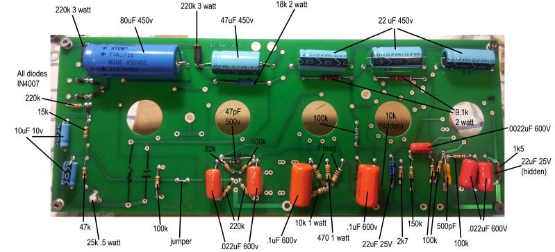
Okay, while I'm waiting for my chassis to arrive, I took the time to populate my board fully and do a quick documentation of the components...
I would GREATLY appreciate it if you all (paging rock_mumbles...) would take a look at it and make sure I'm not missing anything or have otherwise made a mistake.
Please--this is v1, to anyone out there who is building a PCB, double-check these values!!! I'll update it as I get feedback, and I am still planning on making a full layout once I get a blank PCB and the chassis.
[IMG:799:363]http://img.photobucket.com/albums/v519/ ... ed_v1a.jpg[/img]
**Edited for typo'ed PI cap value...hi-res image on page 2 of this thread**
Last edited by mattvon on Thu Aug 23, 2012 6:03 am, edited 2 times in total.
Re: New PCB Express build - seeking advice
mattvon, thanks so much. I just got the bits to start this build. I'll work on finishing the cabinet first. When I start populating the board this will be invaluable. It's so great to have a community like this that shares their knowledge and experience.
Re: New PCB Express build - seeking advice
Hey, I'm just paying it forward! 
All the guys I've had help me, this is the least I can do...but I'd like to make sure my values are correct--I'm hoping rock_mumbles can take a look at it, double-check my work.
All the guys I've had help me, this is the least I can do...but I'd like to make sure my values are correct--I'm hoping rock_mumbles can take a look at it, double-check my work.

Re: New PCB Express build - seeking advice
mattvon, your values are correct.