No problem on the hijack...the build guide calls to connect the center tap to the ground lug under the power cord. I added a ground point for my IEC connector (not a "traditional" 'Wreck build element, but...) so I will likely ground my center tap there.
Anybody else have a better idea/input on this question?
New PCB Express build - seeking advice
Moderators: pompeiisneaks, Colossal
Re: New PCB Express build - seeking advice
Okay, the build continues! After properly grounding my pots (thanks, all!) I wired the IEC, fuse holder, power switch, impedence selector and also the heater wires for all five tube sockets.
Couple of questions--I didn't have any 18-gauge stranded wire on my spools, so I took apart a power cable for wiring up my heaters. It's at least 18-gauge, so I'm good there--but I'm a bit concerned, as I don't know the voltage rating of the wire (no markings on the cable jacket). Is this a potential problem? I can source some proper-rated wire and redo it, but wanted other people's opinions first.
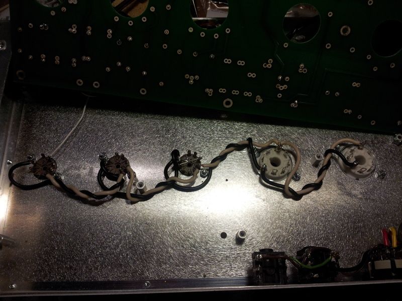
Here's a picture of my wiring...I tried to keep it neat and twisted. I hope it passes inspection!
[IMG:800:600]http://img.photobucket.com/albums/v519/ ... 213045.jpg[/img]
Next question is the Lorlin switch for the impedence selector...it's a weird switch! I don't know if mine is faulty, but it's the oddest thing--sometimes there are three "clicks" or positions and sometimes there are four?!? Continuity test shows that the last pole "moves" on either side of the middle two points. I read somewhere I may have to take it apart to set the number of connections, but I don't know...any ideas? I do have the "proper" Electroswitch called for in the BOM, if that's a better sub.
Thanks for any help in advance!
Couple of questions--I didn't have any 18-gauge stranded wire on my spools, so I took apart a power cable for wiring up my heaters. It's at least 18-gauge, so I'm good there--but I'm a bit concerned, as I don't know the voltage rating of the wire (no markings on the cable jacket). Is this a potential problem? I can source some proper-rated wire and redo it, but wanted other people's opinions first.
Here's a picture of my wiring...I tried to keep it neat and twisted. I hope it passes inspection!
[IMG:800:600]http://img.photobucket.com/albums/v519/ ... 213045.jpg[/img]
Next question is the Lorlin switch for the impedence selector...it's a weird switch! I don't know if mine is faulty, but it's the oddest thing--sometimes there are three "clicks" or positions and sometimes there are four?!? Continuity test shows that the last pole "moves" on either side of the middle two points. I read somewhere I may have to take it apart to set the number of connections, but I don't know...any ideas? I do have the "proper" Electroswitch called for in the BOM, if that's a better sub.
Thanks for any help in advance!
-
rock_mumbles
- Posts: 244
- Joined: Mon Nov 17, 2008 2:03 am
- Location: Podunk, Idaho
- Contact:
Re: New PCB Express build - seeking advice
the heaters are only 6.3V so high voltage wire is not necessary there. It's important to have decent even twists ... some wire retains the twisting pretty well some doesn't ...
I wouldn't use the switch if it has any kind of issues
I wouldn't use the switch if it has any kind of issues

Re: New PCB Express build - seeking advice
The IEC connector should have its own dedicated ground point, very near or next to the IEC socket itself. NO OTHER connections of any kind should be made to this point.mattvon wrote:I added a ground point for my IEC connector (not a "traditional" 'Wreck build element, but...) so I will likely ground my center tap there.
Anybody else have a better idea/input on this question?
The center tap for your PT should be connected where your reservoir capacitor (the first big 40uF cap in the line after the rectifier) makes its connection to ground. Do not be tempted to use the PT's mounting bolts as a common grounding point.
Re: New PCB Express build - seeking advice
Sorry brother, I'm not trying to bust your balls but if you want honesty, I would consider redoing your heater wiring. The Express is not a forgiving amp and can present significant challenges to experienced builders so getting the foundation right before you build the house is critical. You'll want tighter, neater twists and if you can, get the wires to lay flat against the chassis. Any wires reaching up onto the tube socket should retain their twist until the last possible moment before splitting off to their respective pins. You have to consider the big picture and how the individual leads are going to be routed to the tube socket pins (and their relationship to the heater wiring). Everything matters, even things that are seemingly a no brainer.mattvon wrote: Here's a picture of my wiring...I tried to keep it neat and twisted. I hope it passes inspection!
Honestly dude, I would use a 3 position NKK switch. Helluva lot more robust and a helluva lot easier to wire.Next question is the Lorlin switch for the impedence selector...it's a weird switch! I don't know if mine is faulty, but it's the oddest thing--sometimes there are three "clicks" or positions and sometimes there are four?!? Continuity test shows that the last pole "moves" on either side of the middle two points. I read somewhere I may have to take it apart to set the number of connections, but I don't know...any ideas? I do have the "proper" Electroswitch called for in the BOM, if that's a better sub.
Here's the part you want: http://www.mouser.com/ProductDetail/NKK ... jwMfZJo%3d
Here's what it should look like wired up (see attached)
You do not have the required permissions to view the files attached to this post.

Re: New PCB Express build - seeking advice
Apparently some people have not been following the below thread on previously built amps for guidance.
https://tubeamparchive.com/viewtopic.php?t=17524
https://tubeamparchive.com/viewtopic.php?t=17524

Re: New PCB Express build - seeking advice
This helps...however I already cut both center tap wires and attached them to a lug on the PT mounting bolt. Should I splice wire extensions and go under the PCB to the ground point indicated (where the reservoir cap and speaker jack ground)? Obviously this is where you grounded your build, I'm just asking if splicing into the lead is worse than grounding to the OT bolt.Colossal wrote:The IEC connector should have its own dedicated ground point, very near or next to the IEC socket itself. NO OTHER connections of any kind should be made to this point.mattvon wrote:I added a ground point for my IEC connector (not a "traditional" 'Wreck build element, but...) so I will likely ground my center tap there.
Anybody else have a better idea/input on this question?
The center tap for your PT should be connected where your reservoir capacitor (the first big 40uF cap in the line after the rectifier) makes its connection to ground. Do not be tempted to use the PT's mounting bolts as a common grounding point.
To be honest, I looked at your build on the original PCB thread, but other than admiring your workmanship didn't look too closely at all of the connections because you incorporated so many mods. I see now that it's worth looking closely at it as the ground points you used are valuable info.
Re: New PCB Express build - seeking advice
Koop,
I would just leave the taps grounded to the PT since you have already done that no sense moving or extending the wires.
The IEC should have it's own ground point but I have seen commercially built amps run the grounds together?
Mark
I would just leave the taps grounded to the PT since you have already done that no sense moving or extending the wires.
The IEC should have it's own ground point but I have seen commercially built amps run the grounds together?
Mark
Re: New PCB Express build - seeking advice
Okay, thanks for all the suggestions. I'll redo my heater wiring and re-read the PCB thread.
Re: New PCB Express build - seeking advice
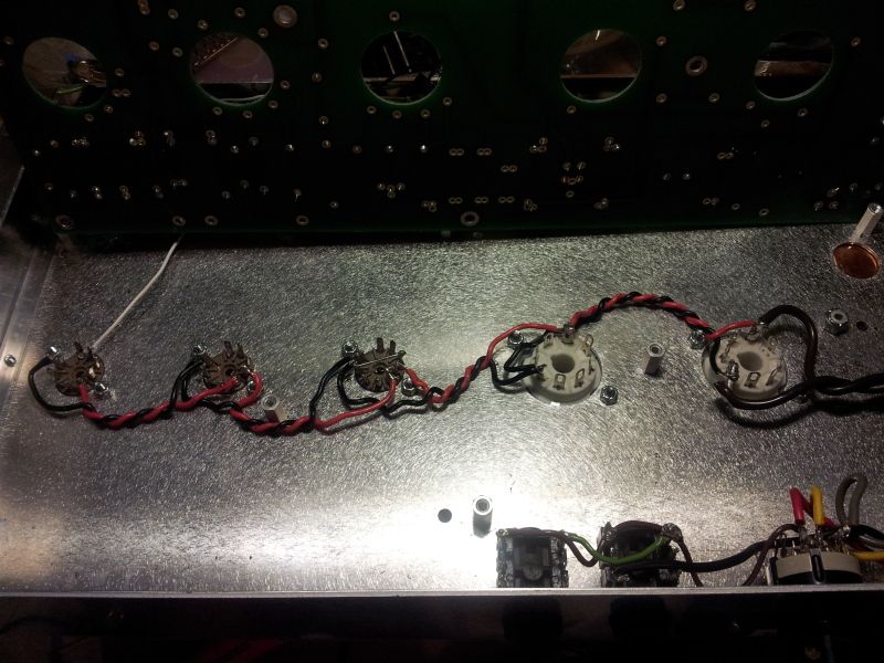
Okay, I've redone my heater wiring and I think it's there now. Please let me know if any of you all think it needs more improvement:
Pic:
[IMG:800:600]http://img.photobucket.com/albums/v519/ ... 215448.jpg[/img]
Like mentioned above, the right wire makes a HUGE difference in getting the wire to twist up well. I ended up buying some 18-gauge stranded wire which did the trick...twisting it in a drill was another great tip.
I've also ordered that NKK switch, I appreciate the heads-up! I got a Fender-style lamp to wire in and then I'm on to the rest of the transformer wiring. Forging ahead!
-
Drew.12345
- Posts: 59
- Joined: Sat Feb 05, 2011 3:58 pm
- Location: Ontario, Canada
Re: New PCB Express build - seeking advice
Matt,
To be honest, I would take a good look at the build guide.
Page 28 shows Ken's style of wiring and I think it may be best to follow this as a guideline.
These are pretty unforgiving amps and I think your wiring is a bit loose on V2 & v3.
Keep the winds tight until the very end as colossal suggested.
Drew
Re: New PCB Express build - seeking advice
Ok, I'll redo the wiring again.
Edit--I guess I'm a bit confused. Page 28 on the guide shows the "lazy loop" method, not tightly twisted at all--in some cases, not twisted a bit. I can redo it mimicking that, but it seems to run counter to all the advice I've gotten in this thread?
Am I better off undoing all the wiring I've done and exactly cloning the lazy loop style on Page 28...or am I better off unsoldering V2 and V3 on my existing wiring and tightening it up from there?
Sorry if I seem dumb--and I HAVE read the guide, several times--but it seems contradictory.
Re: New PCB Express build - seeking advice
You don't seem dumb at all and it's good you're pushing to get it right. Trainwrecks are pretty unforgiving amps so incremental enhancements through good build techniques increase the chances of the amp working and sounding correctly.mattvon wrote:Ok, I'll redo the wiring again.
Edit--I guess I'm a bit confused. Page 28 on the guide shows the "lazy loop" method, not tightly twisted at all--in some cases, not twisted a bit. I can redo it mimicking that, but it seems to run counter to all the advice I've gotten in this thread?
Am I better off undoing all the wiring I've done and exactly cloning the lazy loop style on Page 28...or am I better off unsoldering V2 and V3 on my existing wiring and tightening it up from there?
Sorry if I seem dumb--and I HAVE read the guide, several times--but it seems contradictory.
There are differing schools of thought with respect to heater wiring. The lazy loop method is generally preferred by guys building true replica TW amps. Many builders prefer to minimize coupling effects and maximize noise canceling whenever possible by tightly twisting and ensuring that heater leads run perpendicular to any signal wires or in the Z-axis (see Fender and Dumble builds). It's really up to you, but I think if you look at the gutshots of many, many amps posted here, most builders use a neat/compact approach to heater wiring.
Here's how I did the heater wiring on my TW PCB amp.
You do not have the required permissions to view the files attached to this post.
Re: New PCB Express build - seeking advice
Thanks so much! That's an awesomely neat job of wiring, and one I will try to duplicate tonight. So clean...
Re: New PCB Express build - seeking advice
Right on man. Yeah, just take your time. I twist a red/black pair of 18g stranded copper up in a drill, then cut sections out of it to run from tube to tube. It may take you several attempts to dial it in, so don't worry about it if you mangle a few sections and have to start again. Dry fit each of your wire runs on the socket, tack it in place with a bead of solder, and then flow the holes and clip the excess flush to the pin when you're satisfied with the way the twisted pairs are laying. Be careful if you use solid core wire for your heaters as you don't get more than a time or two of twisting before you can create an internal crack in the wire. Stranded copper is more robust and forgiving.mattvon wrote:Thanks so much! That's an awesomely neat job of wiring, and one I will try to duplicate tonight. So clean...