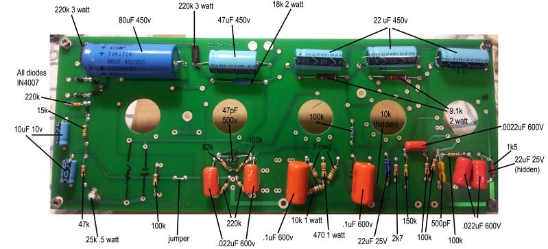
I think C13 and C14 the PI coupling caps should be 0.022uf not 0.22uf
And maybe the 100k and 82k PI plate resistors need to be swapped around ???
New PCB Express build - seeking advice
Moderators: pompeiisneaks, Colossal
-
rock_mumbles
- Posts: 244
- Joined: Mon Nov 17, 2008 2:03 am
- Location: Podunk, Idaho
- Contact:
Re: New PCB Express build - seeking advice
Great catch! That's a typo, I've got 223j caps in there...I'll correct it and repost.
The PI resistor values were confusing to me when I soldered them in...following the schematic and the layout for the scratch build, it seemed I had it right, but it's hard to tell without the tube sockets installed and oriented.
So, in the end, I followed this pic--I know this is the L'pool build...I make the 100k resistor connecting to pin 1 of V3...that look right to you?
-
rock_mumbles
- Posts: 244
- Joined: Mon Nov 17, 2008 2:03 am
- Location: Podunk, Idaho
- Contact:
Re: New PCB Express build - seeking advice
So as far as the PI plate resistors I was looking at the schematic ... looking at a layout it's like the way you have your pcb ... the 100k plate resistor is connected to pin 1 of V3 and then to V4 the 82k plate resistor is connected to pin 6 of V3 and then goes to V5 ...
Could you post a larger picture (at least 2x larger) somewhere?
Could you post a larger picture (at least 2x larger) somewhere?
Re: New PCB Express build - seeking advice
Okay, so I've corrected those PI cap values and left the PI resistor values alone...thanks so much for your help!
Photobucket wasn't willing to upload my pics at the original size, so I'm using Dropbox. Once the link loads, there's a "Full Size" button at the bottom which will blow it up nicely. Let me know if this doesn't work for anyone...
Embedded, Photobucket link:
[IMG:799:363]http://img.photobucket.com/albums/v519/ ... ed_v1a.jpg[/img]
Full-size, Dropbox link:
http://www.dropbox.com/gallery/9502380/ ... s?h=d42b8f

Re: New PCB Express build - seeking advice
I usually just make them 100k/100k rather 100k/82k.
Mark
Mark
Re: New PCB Express build - seeking advice
Okay, good progress tonight! I got my package from rj, awesome quality and service, btw...
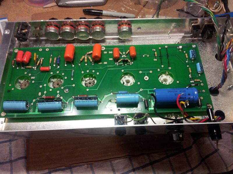
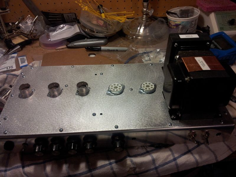
I got a really nice baltic birch headbox and a chassis (and second PCB), so I set about mounting all the components in the chassis.
Tube sockets and transformers, pots and jacks, IEC and fuse holder, all switches...good night's work.
A couple of pics before the soldering starts tomorrow...I'm sure I'll be back with questions...but maybe, with luck, I could be testing out my amp on Sunday!
[IMG:800:600]http://img.photobucket.com/albums/v519/ ... 224122.jpg[/img]
[IMG:800:600]http://img.photobucket.com/albums/v519/ ... 224154.jpg[/img]
Re: New PCB Express build - seeking advice
Your going to enjoy this amp I wouldn't mind building another if I had a PCB from rj.

Re: New PCB Express build - seeking advice
In the first photo I see lines drawn with a sharpie above the power tube socket. It looks like a cap symbol and resistor symbol. Are you missing a couple of parts?
Re: New PCB Express build - seeking advice
When I got the PCB from rock_mumbles, he had laid it out for a L'pool build...those marks are from his original build notes. They are not used in an Express.
I believe I am going to have to jumper one of those locations for the cathode...here is rock_mumbles comment from earlier in the thread:
"You'll have to ground (jumper) either #4 or 5 (the cathodes) ... I'll look at my scans and look at the bias supply ... "
Please note that #4 and #5 in this case refers to my own question, NOT the schematic or layout.
Re: New PCB Express build - seeking advice
Okay, here's the first of what will likely be many questions! 
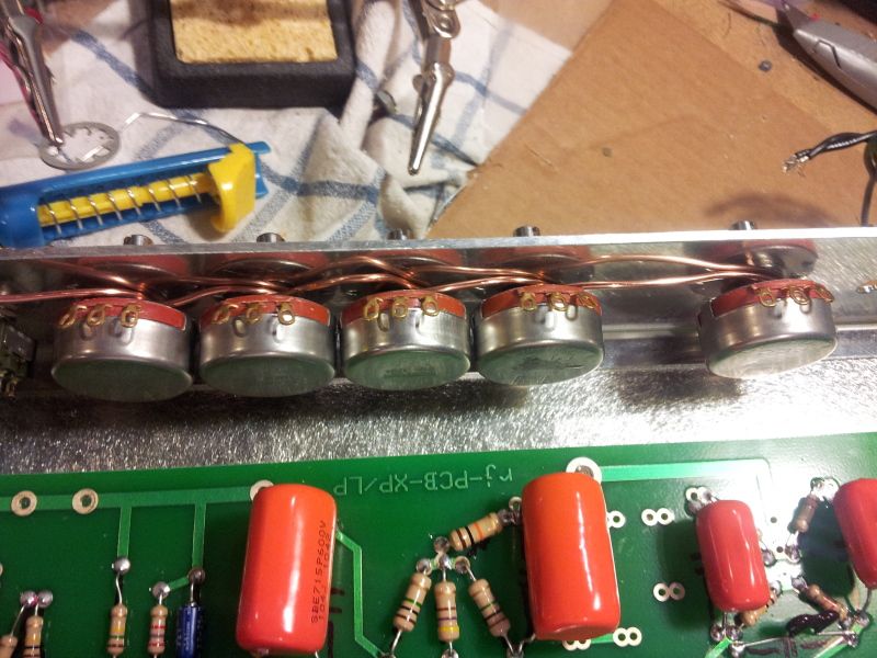
Since I followed the original BOM, I ordered the PEC pots and discovered (d'oh!) I can't solder the ground buss bar to the back of them.
I've looked at a couple of different threads regarding how to work around the issue and have come up with what is likely a dumb solution--I simply wrapped copper wire around the shaft of the pots and tightened down the nuts. To my way of thinking, it accomplishes the same goal, right? Ground is accomplished, at least according to the continuity check on my multimeter...and I can solder short jumpers from the appropriate pot lugs to my copper wire.
I'm concerned about ground loops, etc, so if anyone wants to point me in a better direction, I'd be grateful.
Here's a picture which can either serve as a warning to other guys building this amp...or a helpful reference!
[IMG:800:600]http://img.photobucket.com/albums/v519/ ... 094038.jpg[/img]
-
rock_mumbles
- Posts: 244
- Joined: Mon Nov 17, 2008 2:03 am
- Location: Podunk, Idaho
- Contact:
Re: New PCB Express build - seeking advice
I would support the ground buss by soldering wires to the PEC pot ground tabs, sort of a ladder aarrangement.
The issue I see with having the copper loops is copper is soft enough that your connections may loosen up with time and use.
The issue I see with having the copper loops is copper is soft enough that your connections may loosen up with time and use.
Last edited by rock_mumbles on Sat Aug 25, 2012 3:35 pm, edited 1 time in total.

Re: New PCB Express build - seeking advice
Mattvon, I would recommend against the bus bar. Instead, run your grounds from each of the respective pots which has a ground to the grounding pad on the PCB nearest to the node that that pot serves.
Here is how I did mine:
https://tubeamparchive.com/download/file.php?id=21981
Here is how I did mine:
https://tubeamparchive.com/download/file.php?id=21981
Re: New PCB Express build - seeking advice
Stellar advice, thanks to both of you! I think I'll go with the handily-provided ground nodes on the PCB...another learning moment!
Re: New PCB Express build - seeking advice
I second colossal's note.
Re: New PCB Express build - seeking advice
mattvon, I don't mean to hijack. I hope you don't mind if I piggyback on this thread as I'm almost ready to begin my PCB Express and I'm trying to get my head around it.
My first question is about the grounding scheme. My previous builds only used a few ground points. It appears that the PCB has 7 places where ground is acheived through the stand offs. Where should I ground the PT center tap?
My first question is about the grounding scheme. My previous builds only used a few ground points. It appears that the PCB has 7 places where ground is acheived through the stand offs. Where should I ground the PT center tap?