Hey Matt... sorry to miss your PM. My mom's health has been Poor lately and her care takes a toll on my attention to the amp biz.. with MM on the scene you are in great hands, Martin, this whole forum appreciates what you do!
I am working a lot from my cell phone these days but once I get in front of my compter I'll get you some more info. This build is schematically the same as the standard Express if that helps... except for some small changes like no diodes across the tubes.
New PCB Express build - seeking advice
Moderators: pompeiisneaks, Colossal
-
RJ Guitars

- Posts: 2663
- Joined: Tue Nov 14, 2006 3:49 am
- Location: Los Alamos, New Mexico
- Contact:
Re: New PCB Express build - seeking advice
Good, Fast, or Cheap -- Pick two...
http://www.rjguitars.net
http://www.rjaudioresearch.com/
http://diyguitaramps.prophpbb.com/
http://www.rjguitars.net
http://www.rjaudioresearch.com/
http://diyguitaramps.prophpbb.com/
-
RJ Guitars
- Posts: 2663
- Joined: Tue Nov 14, 2006 3:49 am
- Location: Los Alamos, New Mexico
- Contact:
rj - PCB-LP voltage chart
Edit: Decided to repurpose this debug page...
Here is something additional that should be useful. I'll also admit I have done very little tweaking on this amp and it could certainly be optimized. Most of the component values are still the same as they are on the regular Liverpool schematic.
PCB-LP Voltage Chart
Meas. Point -- VOLTS dc
C17 - 373
C18 - 349
C19 - 300
C20 - 288
C21 - 279
V1 pin 6 - 216
V1 pin 1 - 233
V2 pin 1 - 256
V3 Pin 6 - 241
V3 Pin 1 - 241
V4 Pin 7 - 370
V4 Pin 9 - 345
V4 Pin 3 - 11.4
V5 pin 7 - 372
V5 pin 9 - 346
V5 pin 3 - 11.4
You do not have the required permissions to view the files attached to this post.
Last edited by RJ Guitars on Fri Apr 25, 2014 1:21 pm, edited 2 times in total.
Good, Fast, or Cheap -- Pick two...
http://www.rjguitars.net
http://www.rjaudioresearch.com/
http://diyguitaramps.prophpbb.com/
http://www.rjguitars.net
http://www.rjaudioresearch.com/
http://diyguitaramps.prophpbb.com/
Re: New PCB Express build - seeking advice
Thanks, gents! RJ, no worries--I appreciate all the help you've given with parts, advice, etc.
MM, I've got a 40 watt bulb in the limiter and it's really bright--I'd say it's at full power with the EL34s in it. Did I make a simple rookie mistake by using too small a bulb? It was all I had on hand, but I can easily grab a higher wattage bulb if needed...
Gotcha on the 1R resistor, I'll see what I have at the house.
-
martin manning

- Posts: 14308
- Joined: Sun Jul 06, 2008 12:43 am
- Location: 39°06' N 84°30' W
Re: New PCB Express build - seeking advice
Full brightness from a 40W sounds like too much current. Can you measure voltages at power tube socket pins with the tubes out? That should give some insight. Without the limiter, you would expect zero at 1 and 8, ~3.5VAC on 2 and 7, something above 400 on 3 and 4, and -35 or -40 on pin 5. With the limiter in everything will be low, but in similar proportion.
Re: New PCB Express build - seeking advice
I will measure and post voltages as soon as I get home, I appreciate all the help!
Re: New PCB Express build - seeking advice
Okay, here we are! EDIT: I forgot to mention, these values are without the bulb limiter.
Pin 1/8: 0 VDC for both V4 and V5
Pin 2 and 7: 3.42 VAC for V4
Pin 2 and 7: 3.43 VAC for V5
Pin 3: 417 VDC for both V4 and V5
Pin 4: 412 VDC for both V 4 and V5
Pin 5: -27.89 VDC for both V4 and V5
One thing I noticed--I tried moving the bias trimpot while measuring Pin 5. I didn't get a very large swing either direction (perhaps -2 or -3 VDC) but the odd part is that moving the trimpot either direction from center resulted in a number which was less negative?!? In other words, max CCW resulted in something like -25VDC and max CW resulted in a similar value. Only when it was at "noon" was it more negative (-28 was the most negative value I read).
Do I have the trim pot miswired? And are the low (or less negative) values likely a result of not having the 1R resistors on pin 1/8?
Thanks for all your help!
-
RJ Guitars
- Posts: 2663
- Joined: Tue Nov 14, 2006 3:49 am
- Location: Los Alamos, New Mexico
- Contact:
Re: New PCB Express build - seeking advice
If you don't mind, take a photo for me. I have a lot of photos of mine and I think they show the details very well... maybe we can compare them.
Good, Fast, or Cheap -- Pick two...
http://www.rjguitars.net
http://www.rjaudioresearch.com/
http://diyguitaramps.prophpbb.com/
http://www.rjguitars.net
http://www.rjaudioresearch.com/
http://diyguitaramps.prophpbb.com/
-
martin manning
- Posts: 14308
- Joined: Sun Jul 06, 2008 12:43 am
- Location: 39°06' N 84°30' W
Re: New PCB Express build - seeking advice
The 1R resistors won't make any difference to speak of in these voltages (except of course with power tubes in you should see 40-45mV on pins 1 and 8, indicating 40-45mA of current). Generally your voltages look good, but the lack of range on the bias adjustment is definitely a problem. It would be hard to make a wiring error, but perhaps the pot has been damaged by overheating, or it has a different pin configuration than expected. Bias voltage that is too high (not negative enough) will cause excessive current draw, and that could explain the brightness of the limiter bulb with power tubes in.mattvon wrote:Okay, here we are! EDIT: I forgot to mention, these values are without the bulb limiter.
Pin 1/8: 0 VDC for both V4 and V5
Pin 2 and 7: 3.42 VAC for V4
Pin 2 and 7: 3.43 VAC for V5
Pin 3: 417 VDC for both V4 and V5
Pin 4: 412 VDC for both V 4 and V5
Pin 5: -27.89 VDC for both V4 and V5
One thing I noticed--I tried moving the bias trimpot while measuring Pin 5. I didn't get a very large swing either direction (perhaps -2 or -3 VDC) but the odd part is that moving the trimpot either direction from center resulted in a number which was less negative?!? In other words, max CCW resulted in something like -25VDC and max CW resulted in a similar value. Only when it was at "noon" was it more negative (-28 was the most negative value I read).
Do I have the trim pot miswired? And are the low (or less negative) values likely a result of not having the 1R resistors on pin 1/8?
Thanks for all your help!
Re: New PCB Express build - seeking advice
Just a suggestion: Check that you haven't connected both ends of the bias pot track together, rather than track and wiper.martin manning wrote:It would be hard to make a wiring error, but perhaps the pot has been damaged by overheating, or it has a different pin configuration than expected.
Re: New PCB Express build - seeking advice
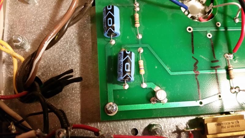
I'm wondering about that as well--here is a picture of the trimpot, perhaps someone will spot a wrong connection:
[img:800:450]http://img.photobucket.com/albums/v519/ ... 74d938.jpg[/img]
It's a bit hard to see, but the arrow is pointing due north in this picture, and that's the midpoint between CCW and CW. I thought the "middle" leg would be the wiper, and that's the end I connected to the resistor. The other two "bottom" legs are connected to ground.
-
martin manning
- Posts: 14308
- Joined: Sun Jul 06, 2008 12:43 am
- Location: 39°06' N 84°30' W
Re: New PCB Express build - seeking advice
Wiper and one end need to go to ground, so I think T-Dog has it. That's consistent with most-negative voltage at mid position too. Probably need to unsolder and rotate it 120 degrees.
Re: New PCB Express build - seeking advice
Gentlemen, I can't thank you enough! I have a working amp!
Plenty of hum, some hiss...but I believe my 50% chance luck was good on the OT, as I've got no squeal.
I put some cruddy tubes in the amp for start-up, so that may be contributing some to the noise. I'll try out some different pre-amp tubes and see how I get on.
Again, this has been an awesome learning experience, but I absolutely couldn't have done it without the help of this forum. Thanks to you all.
Re: New PCB Express build - seeking advice
I can't claim any credit (not that it matters!) - it was the logical conclusion of what you had worked through, and I suspect you had got there before me in any case.martin manning wrote:.. I think T-Dog has it.
Congratulations to mattvon on the build!