
1. I can only see 2 pots in the schematic. Volume after the first 12ax7 and some sort of tone after the third?
2. For the first two preamp tubes the signal comes off the plate and goes to the next stage, yes? But after the 3rd pre tube, its the cathode that's connected to the tone stack (at least that's what I think it is) and then the PI. Why? The more detail, the better.
3. What does the 100pf cap in parallel with the volume pot do? It is some sort of hi or lo pass filter, no?
4. Why is it that only the first 12ax7 has the parallel cap? I thought that was there to block DC, but then why isn't it on the next few?
5. I'm having a little trouble understanding the network of resistors and caps right before the PI (or I guess they're part of it, I should say before the PI _tubes_)?
Mark's Rocket Schem questions
Moderators: pompeiisneaks, Colossal
Re: Mark's Rocket Schem questions
There are two 1M pots in the tone stack, treble and bass. Mid is hard wired via the 1k resistor.benoit wrote:1. I can only see 2 pots in the schematic. Volume after the first 12ax7 and some sort of tone after the third?
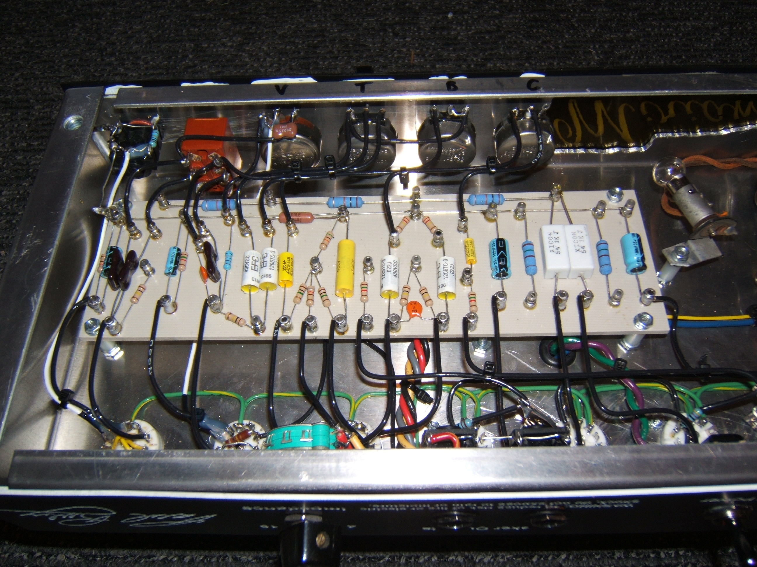
I also add a cut control after the PI but that is not required. Can be seen in this picture well:
http://paulrubyamplification.com/MiriamGuts2.jpg
I even have the labels written on the lip of the chassis: V T B C. That picture is clear enough to draw a full schematic from actually.
That's a cathode follower before the tone stack. The 2nd and 3rd stages are both on the same tube for simplicity. The output of the tone stack comes from the wiper of the treble pot.benoit wrote:2. For the first two preamp tubes the signal comes off the plate and goes to the next stage, yes? But after the 3rd pre tube, its the cathode that's connected to the tone stack (at least that's what I think it is) and then the PI. Why? The more detail, the better.
That's the bright cap. You can see it in my pic above soldered directly to the volume pot.benoit wrote:3. What does the 100pf cap in parallel with the volume pot do? It is some sort of hi or lo pass filter, no?
Just because... Ken Chose not to use a cathode bypass cap on the 2nd stage. However... If you look at my pic, I did choose to use one. Again, the 3rd stage is a cathode follower and thus has no bypass cap.benoit wrote:4. Why is it that only the first 12ax7 has the parallel cap? I thought that was there to block DC, but then why isn't it on the next few?
That's the tone stack.benoit wrote:5. I'm having a little trouble understanding the network of resistors and caps right before the PI (or I guess they're part of it, I should say before the PI _tubes_)?
Finally, looking at my pic, I implemented a "bright switch" that alters both the coupling cap between 1st and 2nd stage (choosing either 500pf or 1000pf) and the treble cap in the tone stack (choosing either 50pf or 500pf).
-
Fischerman
- Posts: 819
- Joined: Thu Dec 07, 2006 3:47 pm
- Location: Georgia
Re: Mark's Rocket Schem questions
paul, nice looking amp. I could probably ask a ton of questions about it but I'll restrict myself to just one: I assume the use of a carbon comp one the V2 socket was intentional; care to elaborate why? Is this one of those rare places where the carbon comp 'resistor distortion' can be realized without the undesirable side effects?
Re: Mark's Rocket Schem questions
Honestly... I cannot hear any difference with carbon comp. But, if they can have an effect, it's due to non-linearity with large DC bias. That only happens on plate resistors it it adds a slight bit of 2nd order harmonics. So, I use carbon comp on plates just in case someone who buys my amp can hear the difference, it gives them the benefit of the doubt...